Hi there!
I'm working in my first ESP32-Cam project and I'm having dificulties to connect to a protoboard and the sensors. All tutorial that i watched it's using a FTDI module and in my case I have the ESP32-CAM-MB, so i'm trying to make the connections for use the ESP32cam board, the programmer board and sensors (DHT11). But I'm not sure if it will work and afraid off do a wrong connection and lost my board.
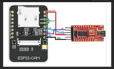
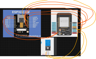
So, I started to connect my circuit using this example. But, instead connect RX to VoT and TX to Vor, I just followed the VOR and VOT correspondent connector in ESP32 CAM MB programmer, with jumpers. Also, I puted the 5V connector to 5V in the ESP32 CAM MB, gnd to gnd. The 3,3V i put in the protoboard to distribute to the sensors and connected the GND/r too. To send the data, i connected the GIO12.
Is there a wrong connection? Can I power the board? haha.
@rodrigocarvo If you have the ESP32-CAM-MB you don't need the FTDI, it's built into the MB part of the board. Just connect your computer to the MB USB connector like any other board. If you are really lucky you will have the version that you don;t need to hold the BOOT button to do an upload.
First computer 1959. Retired from my own computer company 2004.
Hardware - Expert in 1401, and 360, fairly knowledge in PC plus numerous MPU's and MCU's
Major Languages - Machine language, 360 Macro Assembler, Intel Assembler, PL/I and PL1, Pascal, Basic, C plus numerous job control and scripting languages.
Sure you can learn to be a programmer, it will take the same amount of time for me to learn to be a Doctor.
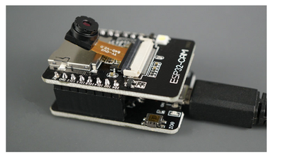
@rodrigocarvo After you plug the ESP32-CAM into the ESP32-MB it will look as follows, now just install the camera and connect the camera to your computer by USB cable. If you need more help, I always check with the nerds at https://randomnerdtutorials.com/upload-code-esp32-cam-mb-usb/
First computer 1959. Retired from my own computer company 2004.
Hardware - Expert in 1401, and 360, fairly knowledge in PC plus numerous MPU's and MCU's
Major Languages - Machine language, 360 Macro Assembler, Intel Assembler, PL/I and PL1, Pascal, Basic, C plus numerous job control and scripting languages.
Sure you can learn to be a programmer, it will take the same amount of time for me to learn to be a Doctor.
Hello @zander!
So, I''m using a protoboard yet to prototipy my circuit. When I connect the esp32-cam to esp32-cam-mb, I lose the jumpers pines and I just can do it using weld. But as i'm still prototyping, I didn't want use weld to build it.
Because of that, I made the connection seems like this exemple with FTDI, but using the MB board. But I don't know if it works haha
@rodrigocarvo The esp32-cam has very few available pins. When using the ESP32-MB board there are NO pins accessible. Because the esp32-cam board has stuff on both sides, it is very hard to work with. Normally it is only used as a camera, but if you need to add a sensor, then some combination of headers both male and female could be rigged up to give you access to the pins. Have you seen Bill's (dronebot-workshop) article and video on this? He overcomes the double sided issue and makes the pins accessible. He also builds a power supply for t that you can choose to do or not, it's not critical to your needs. Here is the article link LINK and video link LINK
BTW, it's called soldering, not welding.
You might also look at the esp eye board. https://www.adafruit.com/product/4095
Also check out Arducam for real cameras https://www.arducam.com
You have not said what you plan on using the camera for but remember it is a 2mp camera. Do not expect good pictures. The Pj and Arducam have much better cameras, I think as high as 8MP which is very good quality.
First computer 1959. Retired from my own computer company 2004.
Hardware - Expert in 1401, and 360, fairly knowledge in PC plus numerous MPU's and MCU's
Major Languages - Machine language, 360 Macro Assembler, Intel Assembler, PL/I and PL1, Pascal, Basic, C plus numerous job control and scripting languages.
Sure you can learn to be a programmer, it will take the same amount of time for me to learn to be a Doctor.
Oh, thanks for the videos and tutorial!! But i guess that i can't make it with the material that i have now. To finish, what to you think about this estrategy of connecting only the pins that could be used, like in FTDI exemple?
Hi @rodrigocarvo,
I have only looked at stuff on the web, not tried it, so I may have missed something.
I think your wiring to FTDI board in your first message is correct. However, experience with different serial/FTDI boards seems to involve some luck, in getting the camera to work. I tried it sometime ago, and after a short battle persuading Windows to connect to the 'FTDI' board, it worked ... but I know others have had a harder time.
Have a look at Bill's (@dronebot-workshop) videos on ESP32-CAM and also ESP32, for some good advice. Also the RND (Random Nerd Tutorials are usually pretty helpful .. e.g. https://randomnerdtutorials.com/program-upload-code-esp32-cam/
Adding a DHT11 is more of a challenge, even though it only needs one GPIO, as I have a feeling, when the FTDI is connected, there are no truly 'free' pins, but I haven't checked that out properly.
One possibility, AFTER downloading your program onto the ESP32-CAM, might be to disconnect the Rx in from the FTDI board, and replace it with the DHT11 data input. Obviously, this precludes using any programs that require data sent from the Serial Monitor at programme run time, and maybe some inconvenience, if developing a program, though a toggle switch might help. Please note, I haven't tried the strategy, so it might fail miserably!
Remember to keep the power to the DHT11 to 3.3V max. Providing you do not exceed 3.3V on a connection to the ESP32-CAM, or something really horrible, like reversing the polarity of the supply, you will be unlucky to damage the board. But all of this is 'experimental', and we all make mistakes to learn from, so there are no guarantees, and the occasional disappointment is part of the cost that most of us have had to pay, before succeeding in the end!
Good luck and best wishes, Dave
@rodrigocarvo You can use the FTDI and even add a temp sensor, but unless you make a carrier board it is tricky to solder the pins as is.
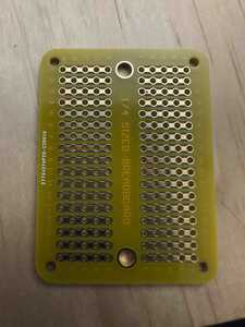
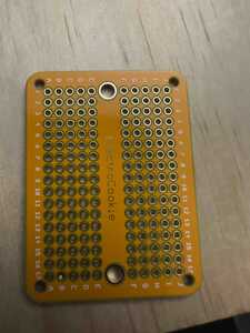
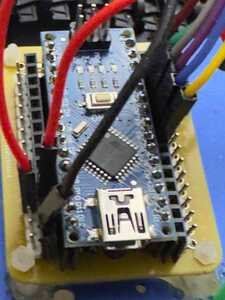
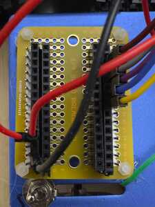
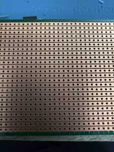
What I would do is get what is called strip board. This is a perf board with the holes connected by copper trace in one direction. Then solder on a female header to attach the esp32-cam. Also solder in another header either female or male next to the first one (I usually do two, one M one F) Now you can use dupont jumpers etc to attach your sensor.
Good luck
I will attach a picture of what I mean later today.
First computer 1959. Retired from my own computer company 2004.
Hardware - Expert in 1401, and 360, fairly knowledge in PC plus numerous MPU's and MCU's
Major Languages - Machine language, 360 Macro Assembler, Intel Assembler, PL/I and PL1, Pascal, Basic, C plus numerous job control and scripting languages.
Sure you can learn to be a programmer, it will take the same amount of time for me to learn to be a Doctor.
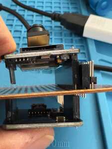
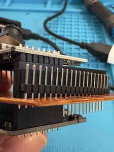
@rodrigocarvo Here are the pictures that hopefully explains what I was talking about. Once you solder the headers onto the permanent breadboard, you can hook up anything you want to the esp32-cam using regular dupont jumpers as shown in the pictyres
First computer 1959. Retired from my own computer company 2004.
Hardware - Expert in 1401, and 360, fairly knowledge in PC plus numerous MPU's and MCU's
Major Languages - Machine language, 360 Macro Assembler, Intel Assembler, PL/I and PL1, Pascal, Basic, C plus numerous job control and scripting languages.
Sure you can learn to be a programmer, it will take the same amount of time for me to learn to be a Doctor.
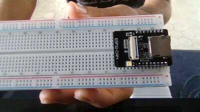
@zander oh! This perfboard looks good! I'll try to find some. but in fact, I suppose there won't be two rows of pins left to place the male and female jumper connectors. unfortunately the esp32cam is larger than this version of the photoas there are 5 perforations in each line, like a breadboard. I will show you a photo that can illustrate it for you
@davee hello dave! thanks for the awnser and the warnings!
but actually, i'm trying to not use the FTDI cause i dont have it, but i have the esp32cam-mb programmer. so i'm making a circuit using some pins of the board and do not connecting the esp32 to the programmer board, cause i've to connect another sensor.
illustrating the circuit. sorry about the drawing. 🙂
Hi @rodrigocarvo,
The limitation of the module covering up the breadboard holes is well known. Some of the other ESP32 dev boards are wider, and cover all the holes! Sometime ago, I published my workaround using a 3D printer.
The approach can also be applied using a simple 'wooden' (e.g. mdf) board, with glue or double-sided tape, though it may not be as convenient and neat as the 3D print.
Note that the commonly available 'bed of holes' boards can be sawn lengthwise, down the middle, without interfering with the connections through the board. They can also be sawn in the middle 'sideways', which is useful to make a 3 or 4 piece version, so that 2 parts hold the ESP32 board, and the other 1/2 pieces hold add-on circuit parts.
See https://forum.dronebotworkshop.com/technology/3d-print-for-breadboard-problem/#post-42337
Best wishes and good luck, Dave
@davee oh, awesome!! this help me a lot. i already cut right now my breadboard hahah
thanks!
the last thing, do you think that i have to do all the connections that normaly are made putting the programmer in the esp32 board, or just the pins that i'll use? i'm afraid about it and thinking that to send data our programming a i have to do this connections.
in the FTDI exemple, it use U0T U0R connections, but i havent certain what is for.
Hi @rodrigocarvo,
Using the MB as a kind of 'FTDI interface' for programming the board, etc. should be fine, albeit I haven't got one, so I have never tried.
-----------
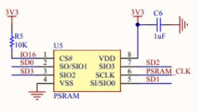
As I was preparing yesterday's answer to you, I noted the Random Nerd Tutorials articles included a discussion about GPIO16, including sentences like:
Hi there, I tried using GPIO16 for a button and found it almost always crashed my ESP32-CAM board. After a lot of head scratching I looked at the circuit diagram and it’s shown connected to PSRAM.
from https://randomnerdtutorials.com/esp32-cam-ai-thinker-pinout/
which is supported by the schematic near the beginning of the same web page, which includes:
I haven't checked it for myself, but it was part of the reason I suggested "there are no truly 'free' pins".
As I haven't physically tested it myself, I am not making any 'definite' predictions, but on the "evidence" I have seen, I would expect problems if any of the software (including the camera software library code) uses the PSRAM, whilst the DHT11 is also connected to GPIO16. Some of the comments on that web page suggest the camera software relies on the PSRAM.
------------------
Hence, I suggested trying one of the pins used for the serial monitor connection, using some kind of manual switching arrangement for the shared pin.
Best wishes, Dave
@rodrigocarvo @davee Bill covered the 'fix' for the wide board problem. I am in Canada and my Amazon is OOS. Here is the board
Jameco Valuepro WBU-204-3-R 1360-Point Solderless Breadboard 6.5"L x 3.1"W
BUT that is not what I showed you, that is THIS again, Canada listing. Just change .ca if it does not do it automatically
HOWEVER
If you want to use the MB assembly, you will need to manufacture some sort of interposer board.
You will need 2 of everything.
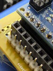
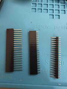
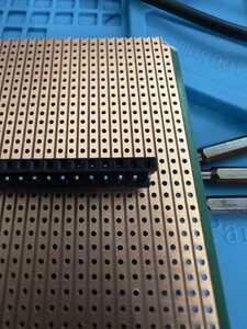
First you need a special header with extra long pins. The camera fits on top and the MB on the bottom but the long pins pass through a strip board so you can add male or female or both headers outboard. See attached pics.
The long pins are actually a bit too long, so either just leave them long, or cut them with std nippers or cut some stripboard oriented correctly a little over 1 hole wide and glue it to the larger board after inserting some pins to align it.
If you can't find parts, let me know your country and I will see what I can find.
The first and 2nd pic is the finished product. The 3rd is the headers, the 4th is the stripboard, the last shows the proper orientation.
BTw, your wiring diagram looks wrong. If you are going to do that, just wire every pin in parallel.
First computer 1959. Retired from my own computer company 2004.
Hardware - Expert in 1401, and 360, fairly knowledge in PC plus numerous MPU's and MCU's
Major Languages - Machine language, 360 Macro Assembler, Intel Assembler, PL/I and PL1, Pascal, Basic, C plus numerous job control and scripting languages.
Sure you can learn to be a programmer, it will take the same amount of time for me to learn to be a Doctor.

