Aim
The "Bed of Holes" Solderless Breadboards are very useful for initially wiring up a small circuit for testing etc., but when used with small processor boards, the processor board often covers most of the holes, leaving few or no holes for wires and components. This post provided the basic design of a very simple 3D print to tackle this problem.
The solution I am proposing is trivial, and I am sure most people who regularly use 3D printers could produce a similar, and probably better, design, but by including my design to use as starting point, I hope to save others a little time and effort. The model is parameterised, so that it can be quickly modified. Please feel free to adapt to your own requirements.
It is not meant to be an example of good design practise ... I am still learning how to use this tool, so please do not be too critical about it, but instead post a better design.
Issue
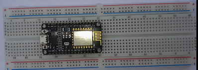
This shows the common MB102 breadboard, with a 1" (25.4 mm) wide processor board. When the processor board is pushed into the holes, for each board pin, only 1 of the 5 holes electrically connected to the board pin is available to insert connection wires, component wires, etc.
Furthermore. many processor boards are wider than this one, making the problem worse.
Solution
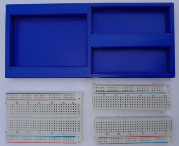
Sawing the breadboard into three pieces provides a convenient set of building blocks. Note that the pairs of power lines on the breadboard only extend over half the length; sawing at the half length point does not break any connections. Similarly, sawing down the middle of the board lengthwise does not break any connections.
The 3D print then provides a tray with appropriate slots to push the pieces into. By suitable choice of hole dimensions, it is possible to use just a friction fit.
Note the breadboard has 3 small lugs on one side of its length. I recommend filing these away, before fitting the breadboard pieces into the tray slots.
---
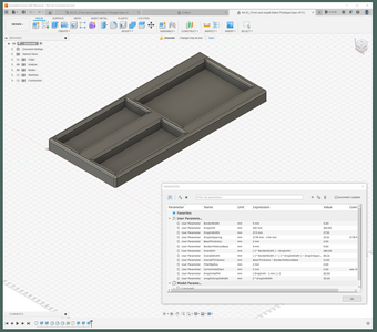
This is the Fusion360 design file - unzip before importing into Fusion 360.
When imported into Fusion360, it should look like this. Selecting Modify, and then Change Parameters will bring up the parameter table shown, allowing dimensions to be changed.
When the required design has been achieved, it can be exported to STL format.
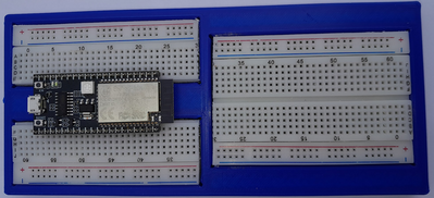
And here is one I made earlier ...
------------
Note
Autocad website says "Fusion 360 is available for free personal use for individuals who are doing home-based, non-commercial design, manufacturing and fabrication projects."
https://www.autodesk.com/products/fusion-360/personal
You will need to create a (free) personal account. The free licence is for 1 year, but my understanding is that Autocad allow it to be renewed annually.
-----------------
Your modified breadboard looks like a good starting point for me even though I have a few of the breadboards that Bill recommended to deal with the width issue (basically a wider centre)
I will try to modify that idea to deal with my other boards that don't work well with a standard breadboard.
Thanks
First computer 1959. Retired from my own computer company 2004.
Hardware - Expert in 1401, and 360, fairly knowledge in PC plus numerous MPU's and MCU's
Major Languages - Machine language, 360 Macro Assembler, Intel Assembler, PL/I and PL1, Pascal, Basic, C plus numerous job control and scripting languages.
Sure you can learn to be a programmer, it will take the same amount of time for me to learn to be a Doctor.
Thanks for the design file, I'll be printing one up soon as its handy to have one a breadboard solution ready to use for the wider boards. I like the corner relief cut outs and the parameter design, very nice. 👍
Regarding the Fusion 360 licence they used to make one re-register each year, but as I'm now over 18 months since to last renewal I think they've opted to let the registration run on these days, probably because they removed a few facilities from their older 'free' package. I cant remember most of what went AWOL as I never use those items, but they now restrict one to have only 10 open designs that can be worked on at the same time time (but seemingly as many other saved designs as desired), but I only work on one design at a time so thats just fine for me 😀
Hi @byron,
Thanks for your message.
I hope it's useful to you. Check the sizes match your needs. They are working for me, but your breadboard might be a slightly different size, and/or my printer might not be accurate. Plus different microcontroller boards are different widths!
I recognise the things you say about the way Fusion360 works now. The 10 open design limit hasn't been a problem either. As you say, you can apparently have as many non-editable designs as you like. I presume this limit applies to doing something clever that requires multiple designs to be open at the same time, but I don't know about it.
Hope you are keeping safe and well. Best wishes, Dave


