Hi @rodrigocarvo,
It looks like our messages are overlapping!
I am a bit dubious about having both +5V and +3.3V connections between the MB board and the ESP32-CAM. As I don't have an MB board, it is tricky to figure out what is going on.
The 'FTDI' style boards are powered by 5V from the USB cable, and generally make that 5V and also 3.3V that they 'make' using an on board regulator, but only one of 5V or 3.3V outputs is then supplied to the ESP32-CAM board. The ESP32-CAM board also has 5V to 3.3V regulator, as all of the ESP32-CAM board electronics requires 3.3V.
Power arrangements for the ESP32-CAM are well known for being 'fragile'. If you are sure both +5V and +3.3V are connected when the boards are directly plugged together, perhaps that helps, even though it would usually be deprecated. I am not really sure - sometimes two bits of not very good design can prop each other up to make a better result than either bit on its own!!
---------------
To program the ESP32-CAM and also provide Serial Monitor, etc. in the Arduino IDE, two connection wires are required, for what is termed 'full duplex' communications. That is:
One connection from a transmit pin (Tx) on the ESP32-CAM sends messages to the receive pin (Rx) on the FTDI interface, and a second connection from the transmit pin (Tx) on the FTDI interface sends messages to the receive pin (Rx) on the ESP32-CAM. For some curious reason, on the ESP32-CAM the Tx pin is labelled U0T and the Rx pin U0R.
These connections are required to program the ESP32-CAM board.
When the ESP32-CAM board is running its programme, then the same lines can be used to write messages on the Serial Monitor screen and send messages to the ESP32-CAM, which is useful for debugging a programme, etc. However, if a pre-programmed ESP32-CAM is separated from its host PC, as might happen for (say) a battery driven application using WiFi for sending images, etc., then these lines are not in use, and with care, might be reassigned to another task. Some care is needed to achieve this, as the pins may need to be given different functions, etc., and debugging writing such functions can be tricky. It depends upon how much 'challenge' you can cope with.
I hope that helps. Best wishes, Dave
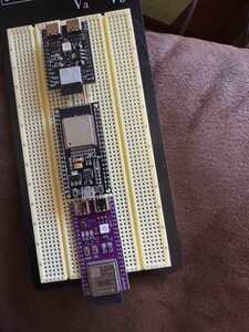
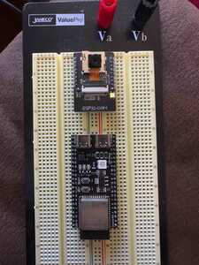
@rodrigocarvo @davee Here is a picture of the board Bill showed us some time ago. I am including pictures with the ESP32-CAM board, and some of the newest ESP32 boards. It seems they are all wider now. That is the special Jameco board I posted above.
First computer 1959. Retired from my own computer company 2004.
Hardware - Expert in 1401, and 360, fairly knowledge in PC plus numerous MPU's and MCU's
Major Languages - Machine language, 360 Macro Assembler, Intel Assembler, PL/I and PL1, Pascal, Basic, C plus numerous job control and scripting languages.
Sure you can learn to be a programmer, it will take the same amount of time for me to learn to be a Doctor.
Hi Ron @zander & @rodrigocarvo,
Thanks, Ron, for your suggestion. I already appreciated Bill mentioned the Jameco board. A quick check (on previous occasions as well as just now) shows it as 'Currently unavailable' in Amazon UK and US, though obviously, other suppliers may be available.
I suspect they would cost more than roughly US$1.50 (equivalent) each, delivered price that I paid. Perhaps, they are better quality, I don't know. I can see some UK possibilities in Google, but they look to be 10 times the cost, and you know I am a skinflint.
I only provided my suggestion as a possibility to consider.
------
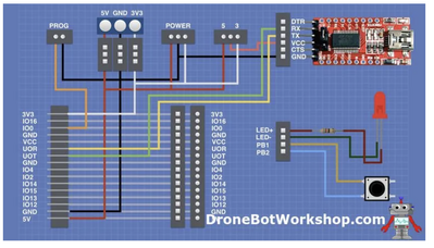
I am not clear about your wiring comment ... I haven't seen one of the 'MB' style bases for the ESP32-CAM, but with the exceptions of GPIO16, plus wiring both +5v and +3.3V, which I have just written about, I thought the sketch shown looked OK, albeit it is tricky to be sure.
However, it has prompted me to look again at the schematic. Apologies, but then I realised I had forgotten to discuss the SDmicro connections, which use several GPIO pins. If someone is not using this in their project, I guess these pins could be used for another device, such as the DHT11. There appear to be 47k pullups on these pins, which should be taken into consideration. I would advise some checking on the web, before rushing into connecting to it, to see if others have experience.
---------
Perhaps the labelling for Tx and Rx on the MB are confusing. The MB board will have a USB chip, possibly by FTDI or maybe something like a CH340, all of which will have a Tx output and Rx input, that will connect through to the complementary Rx and Tx respectively of the ESP32.
It is feasible, that the MB board has been labelled with the same pin names as the ESP32, given that it is the same wire, in which case, Rx would go to Rx/U0R and Tx would go to U0T.
Obviously, it should be wired as if the boards are stacked together.
-----------
I haven't carefully checked the other pins, but at first glance, they seem to be connected to things like the camera, and I assumed they would all be on the ESP32-CAM board, so that wiring down to the MB board would only add opportunities for noise pick up. Have I made a mistake, or maybe I am missing something?
Best wishes, Dave
@davee Indeed OOS here as well. Of course the 3D approach will work as well, I think at the time I did not yet have my printer. If I ever need another one I will probably go that route but I will modify your print so that it more closely resembles the spacing on the Jameco board.
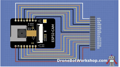
What I was suggesting is to do as Bill did, see pics. Since the esp32-cam is not designed to readily access the other pins because it is sold as a camera, we need to get a little creative. Bill showed one way, I use the MB as I have no need for other pins, and I posted earlier 3 other solutions.
My comment re parallel is similar to Bill's approach, just run a wire from every pin to a shadow header mimicking the same pinout. Now you have 'normal' access to the pins without trying to solder the tops of the pins which is not impossible but if not experienced with a good flux and 700 degree small tip iron is more difficult than the alternatives.
First computer 1959. Retired from my own computer company 2004.
Hardware - Expert in 1401, and 360, fairly knowledge in PC plus numerous MPU's and MCU's
Major Languages - Machine language, 360 Macro Assembler, Intel Assembler, PL/I and PL1, Pascal, Basic, C plus numerous job control and scripting languages.
Sure you can learn to be a programmer, it will take the same amount of time for me to learn to be a Doctor.


