Hello,
I'm still exploring the world of date backs in analog photography.
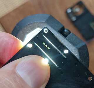
The date imprints are made by shining light through a very small opaque LCD screen
The LCD is controlled like this :
Do you think it would be feasible to use an ESP32 or Arduino to control the digits on the screen ?
How are each segment controlled ?
Thanks
Hi @nicolas,
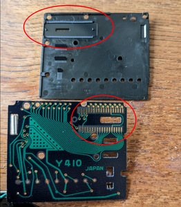
I can only see one side of the PCB without components, and what I assume is a 32,768 Hz crystal lodged in the slot of the PCB.
Similarly I assume it was designed to print a date like 15 11 21 from your other photo for 15 November 2021 ... or possibly 21 November 2015
I am also guessing the other side of the PCB holds 1 or more chips containing a real time clock and LCD driver .. maybe 'borrowed' from an LCD watch design or custom designed for the camera.
The LCD itself appears to have 5 seven segment display 'parts' showing as '8's, plus an extra segment for the '1'. Each segment will require 1 unique connection + at least one common return ... a quick glance at the PCB suggests there may be two connections for the return, that are connected together on the PCB.
Thus there are (5 x 7) + 1 = 35 + 1 = 36 'wires' to drive, not including the common return wire. This obviously requires an 'expander' circuit of some type from an Arduino, with a limted number of GPIO pins!
Furthermore, LCDs normally need to be driven with AC square wave to prevent the electrolyte material being decomposed and severely limiting its life.
So, it maybe possible to build a circuit, but it willl not be a quick and easy fix.
------------
If you wanted to use it as a 'date' stamp, maybe the whole board can be powered and used to provide the date function, as per its initial role. Presumably, it would need at least one switch to perform the initial date setting, and some switching arrangement for the backlight. To me, this sounds a more plausible route, but it is your challenge!
Good luck, Dave
As @davee has pointed out, you'll have 36 LED segments to drive if you want to compose your own dates. Since that exceeds the count available on most microControllers, you'll need to use some additional hardware.
One feasible solution is using a set of shift registers. You can attach a series of 5 of them connected to your controller using only 3 wires to hold all 36 (of the 40 available) bits. You can send the whole pattern down to the registers and then trigger them briefly to flash the date onto the film, then turn them off.
You'll probably need to experiment to get the timing and LED intensity right so that the date appears clearly.
Bill has done a video on shift registers that's worth a watch at ...
Anything seems possible when you don't know what you're talking about.
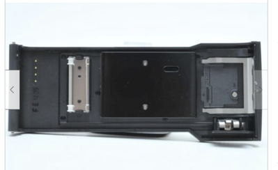
@will FYI @nicolas @davee Here is what an add-on date back looked like. Note there are only 4 connections between the camera front and the back. On the right is where the coin battery went for the lights. The earliest models did not advance the date automatically, the user had to set it with buttons on the back. Later versions of course used an RTC. The DATE back evolved into the DATA back and features like date, time, frame, and time lapse among others were added. See link HERE
First computer 1959. Retired from my own computer company 2004.
Hardware - Expert in 1401, and 360, fairly knowledge in PC plus numerous MPU's and MCU's
Major Languages - Machine language, 360 Macro Assembler, Intel Assembler, PL/I and PL1, Pascal, Basic, C plus numerous job control and scripting languages.
Sure you can learn to be a programmer, it will take the same amount of time for me to learn to be a Doctor.
Sadly, it is (almost certainly, bearing in mind I can only see 2 photos) not as easy as using a few shift registers to do the expanding task --- that is indeed part of the story, but ...
The LCD is likely to be the 'raw' glassware component, with electrode fingers that press onto the surround to make contact. (That interface has a nasty habit of failing with time, but that is another story.)
Each segment of the LCD is a 'classical' capacitor construction, with two transparent conductive plates facing each other. The 'dielectric' is a compound that exhibits liquid crystal behaviour, such as a cyanobiphenyl. This, combined with a polaroid filter on each side of the glass, is the 'whole' component. Although it is possible to build electronics onto the glass plate, this one will be a simple non-multiplexed component. Hence, the voltage waveforms must correpond to exactly what the liquid-crystal material needs - which means connecting directly to the output of a standard 3.3V or 5V logic chip is not a good idea!
The applied voltage is typically small, but needs to be carefully chosen to within a few millivolts as too little or too much tends to result in the whole display area either not changing or all changing to the other state.
Furthermore, the voltage across the segment should be a fairly low frequency square wave to obtain a reasonable lifetime. The dielectric material is fairly high resistance, but a small current flows between the plates. If this current flow is maintained for a period of time, the dielectric will be electrolytically decomposed (same process as the classic conversion of water into hydrogen and oxygen), which will contaminate it, and destroy the liquid-crystalline state.
As the whole task of driving an LCD is rather messy, various chips have been produced. The first one to appear in a Google I just did was:
https://www.nxp.com/docs/en/data-sheet/PCF8553.pdf
At first glance this appears to be about the right size ... 40 segments in non-multiplexed mode, and it performs the square wave drive, etc. functions as well. However, I haven't read the data sheet and I have no data on the LCD, so I do not know whether this one is suitable ... I only reference it as an example of the general type of functionality required. (I also don't know if it is actually available to buy in small quantities.)
Sorry this is another sermon.
Best wishes, Dave
Hi Ron @zander, and @will + @nicolas,
Thanks for the extra information ... I saw the PCB pattern (away from the display) and the corresponding holes in the plastic mount, and wondered if they were for a row of switches .. a quick glance at the link you included gives a clue as to why it used a lot more than 2-3 switches that the most basic functionality would need.
The only component I could see in the photo was metal can towards the left hand side ... of course that could be anything, but it looks like the ubiquitous 32,768 Hz crystal found in practically all 'everyday' real-time clock circuits, so I guess this one could work out the date for itself, once it had been set ... until the battery went flat.
Best wishes, all
This looks really interesting - those pins 🤔 what a nightmare
I don't think you could directly control it with an ESP32, that's where a breakout board would work.
You could use 2 Micro-Controllers if you wish (I would assume you could find a dedicated IC that would allow addressable states in an I2C | SPI configuration)
I'm confident that you could find a chip designed with type of Display in mind
Looks like a fun project, good luck
This One, a long time I have I watched. All this life has he looked away to future, to the horizon. Never his Mind on where he was! what he was doing!
Yoda
I need to bookmark this, the treasures of links 😉
This One, a long time I have I watched. All this life has he looked away to future, to the horizon. Never his Mind on where he was! what he was doing!
Yoda
@nicolas FYI @will @davee @dazza On the standard 4X20 LCD displays you can either use a bunch of wires, or add a tiny board and then it's 4 of which two are - and +. Is it possible the same concept or even the same tiy board can be used with this similar display?
First computer 1959. Retired from my own computer company 2004.
Hardware - Expert in 1401, and 360, fairly knowledge in PC plus numerous MPU's and MCU's
Major Languages - Machine language, 360 Macro Assembler, Intel Assembler, PL/I and PL1, Pascal, Basic, C plus numerous job control and scripting languages.
Sure you can learn to be a programmer, it will take the same amount of time for me to learn to be a Doctor.
@nicolas FYI @will @davee @dazza On the standard 4X20 LCD displays you can either use a bunch of wires, or add a tiny board and then it's 4 of which two are - and +. Is it possible the same concept or even the same tiy board can be used with this similar display?
If you're thinking of the MAX7219 LED drivers, they multiplex to drive each LED separately. So it wouldn't be easy to connect that to the existing wired interface.
I'm wondering if a single pulse of light through each segment is enough to mark the film. It seems that davee is suggesting multiple mild pulses.
Anything seems possible when you don't know what you're talking about.
@will I think it's an I2C connection, the only number on the board is 'I2C-16-V2.1' and the main chip is PCF8574T with +2212 under it.
First computer 1959. Retired from my own computer company 2004.
Hardware - Expert in 1401, and 360, fairly knowledge in PC plus numerous MPU's and MCU's
Major Languages - Machine language, 360 Macro Assembler, Intel Assembler, PL/I and PL1, Pascal, Basic, C plus numerous job control and scripting languages.
Sure you can learn to be a programmer, it will take the same amount of time for me to learn to be a Doctor.
Hi Ron @zander, @will, @nicholas,
Unless I am mistaken, as I can only see the photos, this is 'naked' LCD (not LED, nor is it mounted on a PCB).
This means, I think it is ONLY an LCD ... that it a piece of sealed glassware with no electronics whatsoever.
The connections will be by thin fingers deposited directly onto the glass. This will be pressed against the fingers of the PCB in the photo, with a 'magic membrane' to form a "PCB --> membrane --> LCD" sandwich. The membrane contains conductive stripes in the area touched by the PCB and LCD to make a through 'membrane' connection.
(It should be understood this connection method is 'standard', but is a weakness, which can deterioriate with ageing and does not always appreciate being dismantled and reassembled. 🙁)
-------------
Do not confuse this situation with
- the convenient LCD based displays, (like "4X20 LCD display") readily available from the usual bazaars like Amazon and AliExpress, which come ready mounted on PCBs with electronic interface circuits
- compatibility with LED drivers (like MAX7219 LED drivers).
They all adopt the "8" shape from 7 seven active segments, to make the digits 0..9, but after that they are different!
The electrical voltage and protocol requirements of a 'naked' LCD glasssware display is very different from either of the above mentioned products ( "4X20 LCD display" and "MAX7219 LED driver").
Hence my reference to a chip that specialises in driving LCD displays directly as example of the kind of approach needed.
Best wishes, Dave
@davee I think when that device was current there were no chips. I don't recall seeing what the assembled device looks like but at its most primitive the user manually entered a date either with wheels or pushbuttons. They then enabled the light and the next picture taken would get that date recorded on it.
First computer 1959. Retired from my own computer company 2004.
Hardware - Expert in 1401, and 360, fairly knowledge in PC plus numerous MPU's and MCU's
Major Languages - Machine language, 360 Macro Assembler, Intel Assembler, PL/I and PL1, Pascal, Basic, C plus numerous job control and scripting languages.
Sure you can learn to be a programmer, it will take the same amount of time for me to learn to be a Doctor.
Hi Ron @zander,
I can't see the other side of the board, so it is difficult to be sure, but something has to generate about 37 independent signal voltages to drive the 'fingers' you can see above and below the slot in the top right of the photo, highlighted by the red oval.
And my memory, goes back to era when this type of LCD was the 'new boy on the block', in the early 1970s, which closely corresponded to surge of integrated circuit technology .. AKA 'chips' ... which started in the very late 1960s.
So whilst such cameras are not part of my experience, I don't why how else they would have used, or why they would not have followed the same trends as the rest ... unless you are suggesting the camera shown substantially precedes about 1970?
Best wishes, Dave


