In my project I am attempting to controller a Single Phase Asynchronous Tubular Motor for a projector screen. The specs on the motor are the following:
- 120v
- 0.86A
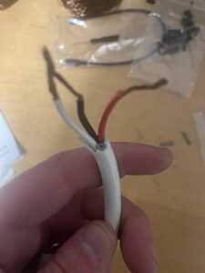
The motor has 4 wires R, B, W, G.
however only three were used in the original configuration (when I bought the screen). The original configuration only had a remote controlled process to raise and lower the screen. I want to implement a more reliable system with up and down buttons hardwired.
I want to use Arduino with some sort of button or switch system that will lower and raise the screen. My first thought was using a relay but not sure exactly how it should be wired in order to get the correct polarity depending on button presses to change direction of the AC motor.
Does anybody have any suggestions or ideas to get this working?
Are there any labels, inscriptions of any sort that a possible Internet search might shine some light?
3 lines of code = InqPortal = Complete IoT, App, Web Server w/ GUI Admin Client, WiFi Manager, Drag & Drop File Manager, OTA, Performance Metrics, Web Socket Comms, Easy App API, All running on ESP8266...
Even usable on ESP-01S - Quickest Start Guide
@dunks44 Since you will be dealing with killing power, and it appears you have no experience with these sorts of projects you need to do quite a bit of studying. Perhaps start with Youtube but also look for written articles, videos are the eye candy, but the written article is the steak.
I am unsure of your intent, if all you want is to eliminate the remote and instead use up/down buttons, that is one thing, but if you want to learn electronics and programming then that is entirely different and will take a lot longer.
First computer 1959. Retired from my own computer company 2004.
Hardware - Expert in 1401, and 360, fairly knowledge in PC plus numerous MPU's and MCU's
Major Languages - Machine language, 360 Macro Assembler, Intel Assembler, PL/I and PL1, Pascal, Basic, C plus numerous job control and scripting languages.
Sure you can learn to be a programmer, it will take the same amount of time for me to learn to be a Doctor.
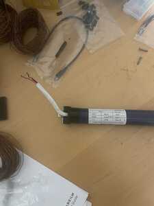
@inq there is only a spec label on the motor Elite Screens EM35SL-6
6NM, 120V, 60Hz, Ø35, 102W, 0.85A, T.P., IP44, Class B.
It also states 33r/min.
I have done some research on Elite Screens motors but this particular motor model does not come up on Elite Screens website.
I am thinking the green wire and black might be (-) or ground, red (+) one direction, white other direction. So on a relay theoretically, if I attach red to NO and black to N than I can add white to normally off and when the relay gets switched off it would reverse polarity from when it was switched on.
But I would need to have an off for the motor so that the screen can stay up or down which might require two relays?
@zander I have done some research on AC and Arduino which is what gave me the relay idea and is actually what brought me to this forum site. Since working with AC isn’t a trial and error process I wanted to reach out to others for insight.
I am just looking to operate with an up and down button.
With a DC stepper motor this would be an easier task but since this is an AC motor it adds complexity.
As this site strives to keep content child-friendly, I must provide the disclaimer. I stay away from house current AC projects. I once built a smart plug with a web interface and power tracking ability. Although tested, I didn't (and won't) use it unattended. You may or may not be a child, but other children may happen upon this thread. Don't do this without adult supervision. Please view/read: https://forum.dronebotworkshop.com/2020/control-ac-devices-with-arduino-safely-relays-solid-state-switches/
Like you, I found very little doing the search: https://www.google.com/search?q=EM35SL-6
Only about 4 or 5 hits. The Images tab had a few pictures and surfing through various candidates, gave even more hits. This one was of interest, but not like yours. You might surf through and stumble upon your motor explained such as:
But I would need to have an off for the motor so that the screen can stay up or down which might require two relays?
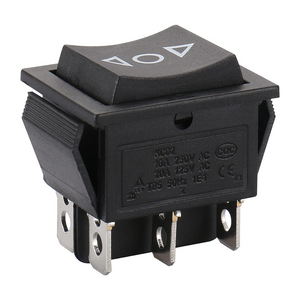
I would think that sounds perfectly logical... you have three modes off, up, down. A simple binary relay can't do that. You can always tie two relays to something like this -
3 lines of code = InqPortal = Complete IoT, App, Web Server w/ GUI Admin Client, WiFi Manager, Drag & Drop File Manager, OTA, Performance Metrics, Web Socket Comms, Easy App API, All running on ESP8266...
Even usable on ESP-01S - Quickest Start Guide
@dunks44 See Bill's video at
and accompanying article at https://dronebotworkshop.com/ac-arduino/
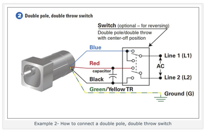
EDIT2: Here is a link that is probably a perfect match for what you have. If you want to use an areduino instead of a hard wired switch, make the appropriate substitutions.
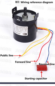
https://gearmotorblog.wordpress.com/2014/06/20/connect-a-reversing-switch/
use #2 diagram
A switch like Dennis showed you in https://forum.dronebotworkshop.com/postid/41208/ is the way to go.
A small motor like that will probably not need any start capacitor and from the sounds of it there is a reduction gear from 3,600 RPM to 33RPM.
EDIT1: Deleted, not needed
EDIT3: If you want to use an arduino and relays, then replace the DPDT switch with relay contacts and with 2 arduino pins for up and down. Logical switch to replace physical switch.
First computer 1959. Retired from my own computer company 2004.
Hardware - Expert in 1401, and 360, fairly knowledge in PC plus numerous MPU's and MCU's
Major Languages - Machine language, 360 Macro Assembler, Intel Assembler, PL/I and PL1, Pascal, Basic, C plus numerous job control and scripting languages.
Sure you can learn to be a programmer, it will take the same amount of time for me to learn to be a Doctor.
Hi @dunks44,
I agree with safety warnings given above and go further ... unless you are totally familiar with working with mains electricity based equipment, find another strategy, such as a low voltage motor ... it is not worth the risk!
As for the motor you have, it may be too late to mention this, but if you still have the original system that powered the motor, then that is your best source of information as to how to connect it, etc. Tracing out the circuit, etc. should reveal what you need to replicate in your improved system. You will of course need to know where each of the motor wires was connected.
Trying to guess what each of the 4 wires of an unknown mains powered motor should be used for, is very hazardous process. On the basis of the very limited information you have provided, this project is presently not safe to proceed with. You might find a combination which apparently works, but is incorrect, causing the motor to overheat or the insulation to break down over a period of time, and then become a shock or fire hazard sometime in the future.
Good luck with your project, but most importantly, stay safe.
Best wishes, Dave
@dunks44 FYI @davee @inq I often mildly disagree with Dave over safety issues. He is VERY strict, while I am a tiny bit more pragmatic. HOWEVER, in this case given your lack of experience you need to listen to him. I used to be an industrial electrician and have over a half century of experience in electronics and mostly mainframe computers so I know how to work safe with a motor like that. You do not!
It would be immensely helpful to see the original circuit and wiring(what wire was NOT connected?), I don't understand what you mean by 'remote controlled process'. Was there an IR or BT remote? If there was, then there was an existing circuit board and it might be easier to tap into it with a simple rocker switch. Pictures of the old PCB might help.
At the moment, there are too many unknowns to allow safe directions.
If you want to proceed then you can't provide too many pictures of the motor, PCB, documentation, web site links etc. Maybe then a safe way forward can be devised.
BTW, what was the original problem that made you want to 'improve' on the existing design?
First computer 1959. Retired from my own computer company 2004.
Hardware - Expert in 1401, and 360, fairly knowledge in PC plus numerous MPU's and MCU's
Major Languages - Machine language, 360 Macro Assembler, Intel Assembler, PL/I and PL1, Pascal, Basic, C plus numerous job control and scripting languages.
Sure you can learn to be a programmer, it will take the same amount of time for me to learn to be a Doctor.
@inq Thank you for the information I was looking at the same switch actually and I will look into the motor as it seems pretty close to mine.
When I found out about the motor being AC I was trying to find a way to drop the voltage for safety reasons using a transformer of some sort but it looks like the motor requires that 120.
Thanks again for the disclaimer and warning. The last thing I want is to promote dangerous activities. I will do a ton more research on safety before attempting.
Thanks again!
@zander Thank you I will look into the links you sent. The video you attached actually is what brought me to this forum. I learned a lot from that video!
@dunks44 FYI @davee @inq I often mildly disagree with Dave over safety issues. He is VERY strict, while I am a tiny bit more pragmatic. HOWEVER, in this case given your lack of experience you need to listen to him. I used to be an industrial electrician and have over a half century of experience in electronics and mostly mainframe computers so I know how to work safe with a motor like that. You do not!
It would be immensely helpful to see the original circuit and wiring(what wire was NOT connected?), I don't understand what you mean by 'remote controlled process'. Was there an IR or BT remote? If there was, then there was an existing circuit board and it might be easier to tap into it with a simple rocker switch. Pictures of the old PCB might help.
At the moment, there are too many unknowns to allow safe directions.
If you want to proceed then you can't provide too many pictures of the motor, PCB, documentation, web site links etc. Maybe then a safe way forward can be devised.
BTW, what was the original problem that made you want to 'improve' on the existing design?
I will post images of the original board and motor later tonight. The old configuration only had an IR remote that got disconnected and would not sync back up with the board. I worked with the company and they sent me another board and remote. I replaced the original with this new board and it too got disconnected after two uses and wouldn’t sync back up.
Because of the above issues, I want to have a “hardwired” solution using a switch or button system.
I do have some experience with main line power as I recently had to require a 4-way switch circuit for a light in my house. Other than changing out a few other switches that’s about all my experience so I appreciate and agree with everyone’s emphasis on safety. I will not attempt this project until I am comfortable with the wiring, power source, and configuration of the system.
@dunks44 Sorry, I can't see anything useful, images are too small.
The following pic should do the trick. Change the Blue in the diagram to your White.
If you want to get an arduino involved, substitute relay contacts for the switch in the diagram then use the switch or a cheaper SPDT to connect to the arduino.
The arduino code is just if UP pressed then write HI to UP relay and the same for the DOWN switch and relay.
Remember to use a small fuse in the L1 or L2 mains power lines.
First computer 1959. Retired from my own computer company 2004.
Hardware - Expert in 1401, and 360, fairly knowledge in PC plus numerous MPU's and MCU's
Major Languages - Machine language, 360 Macro Assembler, Intel Assembler, PL/I and PL1, Pascal, Basic, C plus numerous job control and scripting languages.
Sure you can learn to be a programmer, it will take the same amount of time for me to learn to be a Doctor.
Hi @dunks44,
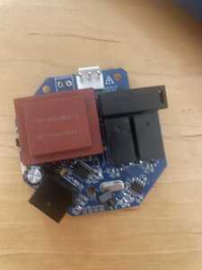
As Ron @zander says, the photos have too low a resolution/quality to see any details, but the circuit board has some components that may be identifiable, and are likely to have the answer to some of your questions, albeit you also need to know precisely how the motor was connected to it.
From what I can see, my guess is the brown square-ish object is a transformer, probably to provide low voltage power for the control circuit, and at a 'wild' guess, given I can't see any printing, some of the black boxes may be relays.
Most components have there type printed on them, and can then be researched on the web, from which a circuit diagram can be created. Not an easy or quick job, but if you can identify parts like relays, which are likely to be used to route power to the motor, then you will probably be able to find te switching circuit, including (if needed) capacitors, etc.
Good luck and stay safe, Dave

