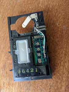
@davee Here is a better view of the device, what can you tell me about this? Still trying to date it.
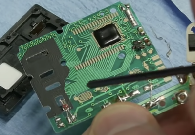
This is a 1990 device. The year can only go from 1990 to 2019. I think there were others before this as well, still looking. I can find 1970's versions of this kind of device but nothing before at least not yet. Therefore that chip like looking part visible in this photo is some sort of clock chip. The OP's images are incomplete so can't tell if it's on the other side or not.
First computer 1959. Retired from my own computer company 2004.
Hardware - Expert in 1401, and 360, fairly knowledge in PC plus numerous MPU's and MCU's
Major Languages - Machine language, 360 Macro Assembler, Intel Assembler, PL/I and PL1, Pascal, Basic, C plus numerous job control and scripting languages.
Sure you can learn to be a programmer, it will take the same amount of time for me to learn to be a Doctor.
Hello,
You totally lost me here 😀
Indeed @zander this video might help you better understanding the electronics :
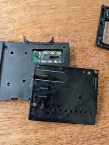
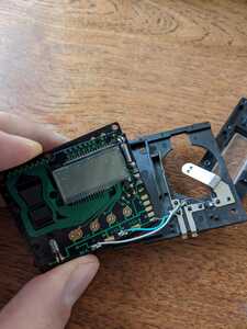
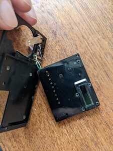
This is from a Minolta F20R (I'm sharing more photos at the end of this post since you all seem very curious :))
What I shared is only the opaque screen, for the moment I'm not interested in the light bulb shining though it or the other screen and buttons used to select the date.
As @davee said the contacts between the screen and the pcb are made via very tiny zebra connector
And as @zander pointed out most of these date modules don't go further than 2019 so my initial thought was to control those "expired" date modules LCD with an arduino so I can "recycle" them to push the date limit further.
From what I understood it won't be easy 😀
Hi @nicolas,
As I expected, there is a 'chip' to drive the LCD .. buried under a rectangular mound of black gunge, shown towards the top-middle part of the photo. It will be a custom chip - possibly directly attached and connected as an 'unpackaged' silicon chip to the board, and then covered with black stuff for protection and mechanical strength.
Sorry, but driving the LCD from microcontroller is feasible, assuming the LCD itself is still functional, but not a 5 minute job.
To do it 'directly', the microcontroller will need to produce about 37 logic signals, albeit shift registers or equivalent could be used, but then each signal will need to produce to appropriate voltage 'on' and 'off' levels, and the polarity will need to swapped many times per second .. hence, the need for chip designed for the job.
The chip I referenced, appeared to produce LCD voltage waveforms, and reduced the microcontroller pin count requirement by including a serial interface, making the proposition somewhat more practical.
Good luck, whatever you decide to do. Dave

