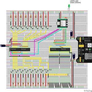
So I have managed to get a few minutes to change the power over to 3.3v for the switches and to pin 16 of the 165. I have changed the MC (ESP32-WROOM-32) and the 165 to a new ones. I had the capacitor (10uf) across the power to the 165 (pins 16 & 8) but added a 100uf across the 3.3v power bus bar.
It's only blooming (nearly totally) working. I can now see a change on the serial monitor for every button pressed. I have removed my High, Low on the clockIn which seemed to fix the duplication button 8 on button2 so the script is back to Bill's original (pin numbers excepted).
I think from here I can move forward to add the 595 as in the third part of the DBW example.
Thanks so much for your pointers DaveE especially the heads up on the 3.3v
Ooops, I did it again!
Hi @mikeburton_2000,
Great to hear you have moved forward.
Although I would 'quarantine' the parts you might have damaged with 5V, I wouldn't bin them ... yet. Some, at least, may have survived. But do label them accordingly, before you forget which is which!!
Hopefully, you will continue to make progress, but please feel free to post if you have further questions or problems.
I would also urge you to try to make some schematic sketches of the circuit, as it is usually much easier to see 'fundamental' problems, like mixing 5V and 3.3V on a schematic, than it is in a photograph. Of course, photographs also contain information that is not on a schematic, so please continue to post them as well!
Whilst, clean CAD drawn sketches are 'nice to see', they are not essential ... hand-drawn sketches with pens and pencils usually convey as much information, and are fine to post.
Best wishes and good luck with your next steps, Dave
Hello again everyone. I think I am just about the point where I give up on this experiment and move on to something else. I cannot for the life of me get it to work how I think it should so there must be something I have not read, missed or just misunderstood.
I have it halfway there, but can't get the last bit right. At the moment what happens is the 16 buttons feed into the two 165 registers. They are passing the info to the XIAO-ESP32-C3. If I serial.print the shifted-in data I see that only 8 digits are present (1111111 when nothing is pressed) and also that buttons 1 to 8 which are attached to the first 165, change the same digits in the serial.print as the buttons 9 to 16. So if I press button 1 I will see:
01111111 and LEDs 1 and 9 illuminate
If I press button 9 I will also see:
01111111 and LEDs 1 and 9 illuminate
This is echoed for all the buttons i.e. button 2 gives 10111111 and LEDs 2 and 10 and button 10 gives the same.
I hope my Fritzing drawing is helpful, as you (good folks of the community) have requested drawings instead of pics, which is understandable. I tried a fritzing schematic, but it looked like Charlottes Web, but with a few unrouted connections. This is also something I must practice further 😉
I have a feeling that there is something to do with the shiftin of the 2 bytes that I have missed and therefor the shiftout is also wrong. I only get a few hours at the weekend to play around with this project and the broken nature of my fiddling doesn't help with my propensity to forget things and I am not sure it is worth the stress at the moment, but I don't like to give up either. Should I be shifting 2 bytes separately instead of trying to shift 16 bits? How and where would be best to do that? Is SPI easier to work with?
Here is my script. The shiftout after initialising serial comm was an experiment as sometimes the setup would power-up with half of the leds illuminated:
// Define the pins for the daisy-chained 74HC165 shift registers
const int loadPin = 2;      // Load pin of 74HC165 Yellow
const int clockEnablePin = 3; // Clock Enable pin of 74HC165 Purple
const int dataPin = 4;      // Data pin of 74HC165 White
const int clockPin = 5;     // Clock pin of 74HC165 Blue

// Define the pins for the daisy-chained 74HC595 shift registers
const int latchPin = 6;     // Latch pin of 74HC595 Orange
const int clock595Pin = 7;  // Clock pin of 74HC595 Blue
const int data595Pin = 21;   // Data pin of 74HC595 Green

int LEDPin = 10;

void setup() {
  // Set pins as inputs or outputs
  pinMode(loadPin, OUTPUT);
  pinMode(clockEnablePin, OUTPUT);
  pinMode(dataPin, INPUT);
  pinMode(clockPin, OUTPUT);

  pinMode(latchPin, OUTPUT);
  pinMode(clock595Pin, OUTPUT);
  pinMode(data595Pin, OUTPUT);

  pinMode(LEDPin, OUTPUT);

  // Enable the 74HC165 shift registers
  digitalWrite(clockEnablePin, LOW);
  digitalWrite(LEDPin, LOW);

  // Initialize Serial communication
  Serial.begin(9600);

  digitalWrite(latchPin, LOW);
  shiftOut(0000000000000000, 0000000000000000, 0000000000000000, 0000000000000000);
  digitalWrite(latchPin, HIGH);
}

void loop() {

  digitalWrite(LEDPin, HIGH);

  // Read buttons states from the 74HC165 shift registers
  byte buttonState = readButtons();

  // Send the button states to the 74HC595 shift registers
  sendTo595(buttonState);

  // Delay for debouncing
   digitalWrite(LEDPin, LOW);
  delay(100);


}

byte readButtons() {
  byte buttonState = 0;

  // Shift in the button states
  digitalWrite(loadPin, LOW);
  delayMicroseconds(10);
  digitalWrite(loadPin, HIGH);
  delayMicroseconds(10);

  for (int i = 0; i < 16; i++) {
    digitalWrite(clockPin, HIGH);
    delayMicroseconds(10);
    bitWrite(buttonState, i, digitalRead(dataPin));
    digitalWrite(clockPin, LOW);
  }

  return buttonState;

 //delay(250);

}

void sendTo595(byte buttonState) {
  // Send the button state to the 74HC595 shift registers
  digitalWrite(latchPin, LOW);
  shiftOut(data595Pin, clock595Pin, LSBFIRST, ~buttonState);
  digitalWrite(latchPin, HIGH);

  Serial.println(buttonState, BIN);
  delay(100);
}
Again, any pointers from the members of this community would be greatly appreciated.
Ooops, I did it again!

