3 lines of code = InqPortal = Complete IoT, App, Web Server w/ GUI Admin Client, WiFi Manager, Drag & Drop File Manager, OTA, Performance Metrics, Web Socket Comms, Easy App API, All running on ESP8266...
Even usable on ESP-01S - Quickest Start Guide
@davee I knew I couldn't fool you, but the opportunity to have some fun with you and the AI boys was too much for me to resist. What you are looking at is the AI response to the question of
What wire size is needed for 36V @ 1.5A for a one way 10ft wire
Woz is right
First computer 1959. Retired from my own computer company 2004.
Hardware - Expert in 1401, and 360, fairly knowledge in PC plus numerous MPU's and MCU's
Major Languages - Machine language, 360 Macro Assembler, Intel Assembler, PL/I and PL1, Pascal, Basic, C plus numerous job control and scripting languages.
My personal scorecard is now 1 PC hardware fix (circa 1982), 1 open source fix (at age 82), and 2 zero day bugs in a major OS.
@davee One perhaps final point. I feel as though nobody noticed the following at the top of the 'powerstream' website. I mentioned earlier that there are several different codes/standards etc covering wire. They don't necessarily agree because of safety concerns for one standards group being different than another or even worse, one code/standard/formula is just theory and math with no reservations, and another scales the resultant math to provide human and structure safety considerations. Am I clear?
Definition: ampacity is the current carrying capability of a wire. In other words, how many amps can it transmit? The following chart is a guideline of ampacity or copper wire current carrying capacity following the Handbook of Electronic Tables and Formulas for American Wire Gauge. As you might guess, the rated ampacities are just a rule of thumb. In careful engineering the voltage drop, insulation temperature limit, thickness, thermal conductivity, and air convection and temperature should all be taken into account. The Maximum Amps for Power Transmission uses the 700 circular mils per amp rule, which is very very conservative. The Maximum Amps for Chassis Wiring is also a conservative rating, but is meant for wiring in air, and not in a bundle. For short lengths of wire, such as is used in battery packs you should trade off the resistance and load with size, weight, and flexibility. NOTE: For installations that need to conform to the National Electrical Code, you must use their guidelines. Contact your local electrician to find out what is legal!
I have highlighted certain sections of the above to emphasize the point.
All your math and theory you have so carefully researched is no doubt accurate but it fails to take into account legal precedent (especially in NA) and organizational codes/standards. Since we have a much safer mains system here albeit at the cost of efficiency, the NA approach must be different than the rest of the world.
Bottom line is I think you and I agree that 18AWG to 22AWG or maybe even smaller will do the job for Dennis (@inq).
Getting back to the OP, the reason why the two columns for Max Amps are so different is due to many considerations, some of which are not based on the laws of physics, but instead take into account precedent, field practice, legal, and safety. In other words, there is no simple answer.
That's all folks.
First computer 1959. Retired from my own computer company 2004.
Hardware - Expert in 1401, and 360, fairly knowledge in PC plus numerous MPU's and MCU's
Major Languages - Machine language, 360 Macro Assembler, Intel Assembler, PL/I and PL1, Pascal, Basic, C plus numerous job control and scripting languages.
My personal scorecard is now 1 PC hardware fix (circa 1982), 1 open source fix (at age 82), and 2 zero day bugs in a major OS.
Hi Ron @zander,
Perhaps this actually shows you need to find a better AI system? Did you use an Apple one? 🤔 🤔
----------------------------------------------------------------------------------
Bing's Chat fed wiith the same question ...
To calculate the wire size needed for a 10ft one-way wire carrying 36V at 1.5A, we can use a wire size calculator. One such calculator is available at 1.
The calculator requires the following inputs:
- Voltage drop (V): 36V
- Current (I): 1.5A
- Distance (D): 10ft
- Material: Copper
Using the calculator, we get that the minimum wire gauge required is 16 AWG 1.
Please note that this is only an estimate and other factors such as temperature, insulation, and other environmental conditions may affect the actual wire size required.
1. omnicalculator.com2. omnicalculator.com3. learnmetrics.com4. wiresizecalculator.net5. wiresizecalculator.net6. calctool.org
---------------------------------------------------------------------------------------
As I have said, @Inq's case is unusual, whilst this is a somewhat 'generic' answer, but many people would find the list of references a useful start.
Not a full scholarly response of course, but equally not all rubbish. These systems are only early babies ..
And using the first reference calculator:
-------------------------------------------------------------------
-------------------------------------------------------------------
Best wishes, Dave
Hi Ron @zander,
Of course, there are legal, etc. rules around the World, which in the main are aimed at safety .. and because the rules must be written such that can be understood and applied by a large number of people, in a huge range of circumstances, so they will always be conservative.
Dennis @Inq's case is very unusual, but so far as I ascertain, only a modest risk.
So, I took care to warn Dennis @Inq that my suggestion was pushing towards every limit, though hopefully not over the limits, but with no guarantees.
Hence, I don't feel too bad about suggesting very thin wires .. 26 to 30 AWG, depending upon motor characteristics and current settings .. but obviously only for this specific case, by Dennis himself ... not for general application.
And I did take the header into account .. in particular the explanation "The Maximum Amps for Chassis Wiring is also a conservative rating, but is meant for wiring in air, and not in a bundle. ", which compares well to Inq's wiring in air, and a 'bundle' of just two wires, for which I included an estimate based on the Tool Box data table trend .. ie a derating of 65-70%.
Best wishes, Dave
@inq
I moved this over here. @thrandell prefers me to not distract from his thread too much. So I try to keep my posts there as pertinent to his project as I can and as concise as I can (and often fail).
This is the weakness I mentioned earlier where you can't edit posts after 1 hour. Ideally the first post is where you could add to and edit the project so that any new reader doesn't have to wade through all the other posts to find out the latest version or an old reader need to search for something like that link to a slip ring.
https://www.adafruit.com/product/736#tutorials%5D
The only other option is to have your projects on your own web page.
@davee Nothing Apple about it, it was Google's Bard that just crossed my desk yesterday.
First computer 1959. Retired from my own computer company 2004.
Hardware - Expert in 1401, and 360, fairly knowledge in PC plus numerous MPU's and MCU's
Major Languages - Machine language, 360 Macro Assembler, Intel Assembler, PL/I and PL1, Pascal, Basic, C plus numerous job control and scripting languages.
My personal scorecard is now 1 PC hardware fix (circa 1982), 1 open source fix (at age 82), and 2 zero day bugs in a major OS.
Hi Ron @zander,
In the UK, and especially in the area of Straford-upon-Avon, not many miles North of where I am presently, 'The Bard' would normally conjure up the thought of a certain William Shakespeare, who you may have heard of. 🤔
Whilst Wikipedia ( https://en.wikipedia.org/wiki/Bard) offers:
In Celtic cultures, a bard is a professional story teller, verse-maker, music composer, oral historian and genealogist, employed by a patron (such as a monarch or chieftain) to commemorate one or more of the patron's ancestors and to praise the patron's own activities.
With the decline of a living bardic tradition in the modern period, the term has loosened to mean a generic minstrel or author (especially a famous one). For example, William Shakespeare and Rabindranath Tagore are respectively known as "the Bard of Avon" (often simply "the Bard") and "the Bard of Bengal".[1][2] In 16th-century Scotland, it turned into a derogatory term for an itinerant musician; nonetheless it was later romanticised by Sir Walter Scott (1771–1832).
Perhaps Google named their offering on the basis of their understanding of its capability?
However, finding a failed attempt at something is very flimsy evidence about the limits of what can be achieved.
------
More seriously, it is good to hear you were trying to pull my leg and that you realised it was gibberish as well ... I was actually concerned your health had taken a bad turn, and that you were confused.
Take care my friend and try to remember April Fool's day happens in April ... not September. 😉
Best wishes, Dave
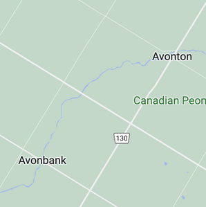
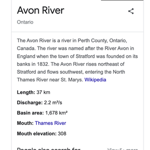
@davee But nobody expects it in September. Not to worry, we here in the colony also celebrate the Bard, I lived within a short drive of Stratford, Ontario, where there is not only the Avon river, but also the Thames, and London, Ontario, plus a few more like names. I am attaching some pics to show you I am not playing tricks.
By the way, a lot of my ancestors are from that area since they go back something like 6 generations. When doing my family tree, I even visited distant cousins in that general area.
Here is an interesting link LINK, and this is a Google Street View I think. Click the arrows LINK
I think every Southern Ontario and maybe more high school student in grade 9 is offered a school trip to Stratford to see a Shakespearean play. I know I attended and enjoyed it very much, although I barely understood a word they spoke.
First computer 1959. Retired from my own computer company 2004.
Hardware - Expert in 1401, and 360, fairly knowledge in PC plus numerous MPU's and MCU's
Major Languages - Machine language, 360 Macro Assembler, Intel Assembler, PL/I and PL1, Pascal, Basic, C plus numerous job control and scripting languages.
My personal scorecard is now 1 PC hardware fix (circa 1982), 1 open source fix (at age 82), and 2 zero day bugs in a major OS.
@inq wrote
My main goal with Inqster was to study Artificial Intelligence (AI) using Artificial Neural Network (ANN) and Genetic Algorithms (GA). The main aspect about using either method, is the bot learns how to run the bot. I don't have to explicitly write code to use sensors to say... something is in the way, go around it. Like a child, the bot needs to run into it half-a-million times, say ouch and finally veer around it.
I'll start out using ANN techniques versus GA as it just makes more sense to my brain.
They both use an ANN, you mean backpropagation to adjust weights vs genetic algorithms to evolve a set of weights.
The advantage of backpropagation may be the potential ability for the individual robot to adapt to a change in the environment.
In my simulations I used two fitness factors.
1. Cover sufficient area in a certain time limit
2. Not hitting anything.
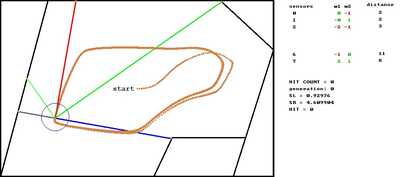
There are only 10 weights to find for 10 sensor inputs. So if the weights were limited to 0 to 9 in steps of 1 then there would be 1,000,000,000 possible combinations. Fortunately, as in the biological world, there may be a large number of working solutions so one of them will be found without trying every combination. The example below took less than 100 random trials and only used weight values 0 to 9.
All the "solutions" can fail catastrophically just like the commercial neural nets when something pops up not found in the training set.
Now for backpropagation you need an error signal that comes from comparing the actual output with the desired output for any given input. This is simpler if say the inputs are a collection of cat images and a collection of dog images and you want it to output a high value on the DOG output or a high value on the CAT output. You know what the input class is and what output you want to assign to that class.
Remember a neural net is not a stand alone brain. It is not that simple. There are different types of neural nets and they are supported by a lot of tweaking and additional code. For example a neural net that returns a value CAT in rectangle area Xpos, Ypos, width, height then needs you to write code to decide what to do with that information.
With TD-BACKGAMMON that used a neural net to value game states the computer would play thousands of games to the end and then go back over all the stored moves to adjust the weights. That would be like running your robot until say it hit a wall then going back over all the input/output values to adjust the weights. Or maybe just the last few input/output values would do.
https://en.wikipedia.org/wiki/TD-Gammon
A point made by Steven Pinker in his book "How the Mind Works" is illustrated in this program.
"TD-Gammon's strengths and weaknesses were the opposite of symbolic artificial intelligence programs and most computer software in general: it was good at matters that require an intuitive "feel" but bad at systematic analysis."
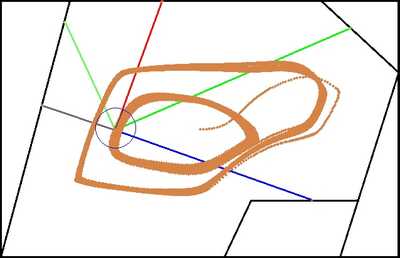
While writing this post the simulation was still running and when I went back to end it I found that the robot had flipped into another cycle! Chaos theory 🙂
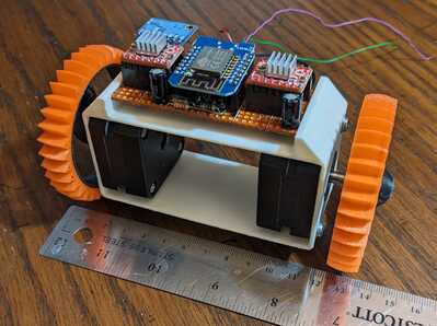
Wanted to pop out an update. I've been working on my custom stepper driver with a few InqEgg customizations. It is written with two steppers in mind and can synchronize them when needed, and count steps. Mainly thought... it is so I can run them faster, harder and more efficiently. It has one main feature that the normal Arduino stepper driver or even Accel Stepper driver doesn't. It has sort-of a transmission.
A stepper can only be driven so fast. If it is in full step mode, it can drive very fast, but it has very course resolution, is noisy and can easily miss a step if trying to accelerate it too quickly. If using micro-stepping (in this case 16x) it has very fine control for very slow, accurate movements. One micro-step equates to 0.069 mm! At rest the driver, drops into first gear like any good automatic transmission. At a certain speed, it'll kick into non-micro-stepping mode for the rest of the way up to top speed. This occurs independently on the two steppers as when it would be making a carving turn, the inner wheel is running a little slower, thus needing to change gears a little later. The driver also automatically disables the steppers when sitting idle. Dropping the current from about 1A to 0.13A for the whole bot.
Some other updates. Fortunately, I double checked my buck converter before cranking up the juice. It is only capable of handling 23V input instead of the 32V I was hoping for. As a result, I decided that I'll run the bot on the nominal 4S 18650 LiIon of 14.8V since I want the learned brain to deal with the inertia and power that it'll have when un-teathered.
Turns out this is no big deal. The following test is using A4988's since they were already on the motherboard, tuned and ready to go. I will try the DRV8825 drivers, but unless I actually need the extra current they supply or go up to 32x micro-stepping, I'm not sure they'll be needed. The following video, isn't that realistic as its mainly a top-speed run of the bot in free air. Although not having contact with the ground the torque at top speed seemed to be adequate to have actually getting it to that speed. 😆 The top speed is totally bonkers and will never be usable with such a small bot... it'd go topsy-turvy long before reaching it.
The Cliffs-Notes
- Drive voltage = 14.8V
- Idle current/wattage = 0.13A, 1.97W
- Peak current/wattage = 1.2A, 17.76W*
- Positional resolution = 0.069 mm
- Top speed = 14.5 mph
* Peak current/wattage seemed to be at near still to about walking speed. At the top speed, it was only pulling 0.37A / 18.3W
3 lines of code = InqPortal = Complete IoT, App, Web Server w/ GUI Admin Client, WiFi Manager, Drag & Drop File Manager, OTA, Performance Metrics, Web Socket Comms, Easy App API, All running on ESP8266...
Even usable on ESP-01S - Quickest Start Guide
Wanted to pop out an update.
Pop one out ? Is this a continuation of your "Birthing babies is hard work" theme ?
I'm curious why you didn't implement a staged stepping solution (kinda like running through the gears on a car), with say going from 16 to 8 to 4 to 2 to single-stepping. Wouldn't that have been easier on the motor and driver than going from 16 to 1 all in one shot ?
Anything seems possible when you don't know what you're talking about.
Pop one out ? Is this a continuation of your "Birthing babies is hard work" theme ?
I'm curious why you didn't implement a staged stepping solution (kinda like running through the gears on a car), with say going from 16 to 8 to 4 to 2 to single-stepping. Wouldn't that have been easier on the motor and driver than going from 16 to 1 all in one shot ?
You know... I should have caught the theme.
Four on the floor! I think I was going for easier on the developer. 😉 The transmission idea is in Inqster Jr also. I did the just the 2-speed transmission (thinking about a follow-on as you suggested). There were a lot of teething problems getting the synchromesh for smooth transistions. IOW, it would be humming along accelerating and the gear shift either jumped too far ahead, or worse back and since they can happen at different times on each side, it tended to step-out like an old Trans Am with a quick-shift kit. I finally got it so it meshed perfectly and you couldn't see any squirrelly behavior, but you could hear the up/down shift.
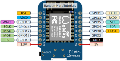
Anyway, the main reason... limited pins using the WeMos
- D0 = Left Gear change
- D1 = SCL for I2C accelerometer, gyro, magnetometer, barometer, ToF
- D2 = SDA " " " "
- D3 = Right Gear change
- D4 = Enable/Disable (both steppers when idle)
- D5 = Left Step
- D6 = Left Direction
- D7 = Right Step
- D8 = Right Direction
- A0 = Analog for battery voltage reading.
That pretty much ate all the pins on the WeMos. For every other gear change, I'd need two more pins.
3 lines of code = InqPortal = Complete IoT, App, Web Server w/ GUI Admin Client, WiFi Manager, Drag & Drop File Manager, OTA, Performance Metrics, Web Socket Comms, Easy App API, All running on ESP8266...
Even usable on ESP-01S - Quickest Start Guide
@inq Multiplexer?
First computer 1959. Retired from my own computer company 2004.
Hardware - Expert in 1401, and 360, fairly knowledge in PC plus numerous MPU's and MCU's
Major Languages - Machine language, 360 Macro Assembler, Intel Assembler, PL/I and PL1, Pascal, Basic, C plus numerous job control and scripting languages.
My personal scorecard is now 1 PC hardware fix (circa 1982), 1 open source fix (at age 82), and 2 zero day bugs in a major OS.
A NodeMCU would be easier, but really two gears get the extremely fine control to position and turn in small fractions of degrees for if/when I start scanning/mapping rooms. 0.069mm position, and 0.066°. And you can't make it go faster than with full-steps.
I've left some gas in the tank. The 100,000 micro-steps equates to 1875 rpm. Supposedly people have gotten close to 3000 rpm. However... they also said, when it throws a rod, it fries the driver and the microprocessor. Something about back EMF at high speed overcoming some part or the other. Steppers make good generators. 😆
Besides... 15mph for an inside bot is a little overkill even for my lead-foot... don't you think?
3 lines of code = InqPortal = Complete IoT, App, Web Server w/ GUI Admin Client, WiFi Manager, Drag & Drop File Manager, OTA, Performance Metrics, Web Socket Comms, Easy App API, All running on ESP8266...
Even usable on ESP-01S - Quickest Start Guide

