Crazy_Blink
A Grim Fairy Tale Marriage of Two Arduino IDE Sketches
Part 1 – Introduction, Outline and Hardware
Introduction
This is intended to be a beginner’s introduction into how to merge two merge two Arduino IDE sketches to form a single programme. There are many example sketches available from multiple sources, including the Arduino IDE built-in examples and provided by third-parties, including the Drone-Bot Workshop and GitHub. A common requirement is to merge two or such examples into a single programme, but this aspect of embedded programming seems to have been largely overlooked. Of course, many people have a professional programming background, including extensive experience in C and C++, who will regard this aspect as straightforward, but it can be more daunting for those coming from other backgrounds.
A comprehensive tutorial on the subject could probably fill a dedicated course, and require the learner to do numerous exercises, so this will only be an introduction, which aims to provide a simple framework and some explanations of what to look for. Equally, some sketch combinations will be much simpler than this example. So please treat this an introduction to some of the possibilities to consider, analogous to introducing a box of new tools. For a specific job, some of the tools might stay in the box, just choose the ones you need for the occasion.
Nevertheless, it is presented as a tutorial, encouraging the reader to perform the typing and editing to get more familiar with the process, rather than just copying and pasting entire scripts. Screen captures of some of the resulting edits are provided for checking purposes.
It assumes the reader has worked with a few example Arduino sketches, and understood the basics of the programme in each case, but may not have noticed some of the more ‘subtle’ aspects of the Arduino IDE, which have been cleverly arranged to minimise the complexity of embedded programming. The example has deliberately chosen to make a very simple, but sadly uninteresting and contrived programme, in the hope that the reader can concentrate on some of the issues concerned with merging two scripts.
Thus the reader is respectfully asked to treat this topic as a ‘Grim Fairy Tale’ and disregard any (patently obvious) thoughts that this project is too simple to require such a complex process.
----------
Although a ‘one size fits all’ recipe is impossible, it is hoped that the reader will then be able to apply a similar approach to far more novel and useful projects. However, compiling this guide is in itself an experiment, and I invite suggestions as to how it can be improved, comments on which parts are successful or not, and so on.
It has deliberately been kept to a very simple hardware requirement and only uses C language constructs. I appreciate that C++ ‘extensions’, when compared to C, offers more tools for the toolbox. Others may point to other languages, particularly Python, offering advantages, albeit using other IDEs.
-----------
For convenience, this topic has been divided into multiple parts; readers encouraged to regard the end of each part as time to take a break, and then review that part, before proceeding to the next part.
Outline of the Project Plan
It is common to start with a general concept of what a project (or programme) should achieve. It is a good idea to document that concept at this point, before thinking about how to achieve it.
While simple projects may present an obvious programme structure that can be coded immediately, in many cases it is better to break the task into two or more mini-projects, each of which produces a contribution to the full project, followed by integrating these contributions into the completed project.
For example, consider an embedded microcontroller project, with a microswitch, acting as a position sensor, and an LED (light emitting diode) acting as an indicator, with a programme executing on the microcontroller, that uses the signal from the sensor to control the LED on and off.
NB For an example of suitable code for such a microswitch project, use the Arduino IDE to find the example sketch Button, by following the path starting from File in the title bar menus:
File → Examples → Built-In Examples → 02.Digital → Button
-------------------------
While this task is simple enough to find or create in a single short programme, now consider the case when the microswitch is replaced by a sophisticated sensor for remote sensing, and the LED is replaced by a motorised actuator, and both the sensor and actuator need many complex interactions with the microcontroller.
It soon becomes apparent that it maybe more convenient to split the programming task into three (or more) parts, e.g.:
-
Fetch data from position sensor
-
Send commands to motorised actuator
-
Combine 1 and 2, so that the incoming position data, automatically commands the motorised actuator
Now, if we are ‘lucky’, we may find example sketches that assist with the first two tasks. But as we are designing a ‘new and novel’ machine, we may need to do the third task ourselves.
Note, that even when parts if 1 and 2 are based on example code that is obtained for elsewhere, it makes sense to implement them on a local ‘test set’, and ensure they each independently function, as expected, so that during part 3, we know any bugs, etc. are as a result of the actions of creating the part 3 code, and not problems with the code from parts 1 and 2.
----------------------
In reality, the last sentence has a good deal of truth, but it is naive. There is a significant risk that something in parts 1 and 2 will have been forgotten or misunderstood, meaning they will require editing and retesting. Furthermore, it may be necessary to modify parts 1 and 2, to enable them to co-exist in the same programme.
So, at this point, a small twist in the plot is introduced to this topic’s Fairy Tale:
Instead of simply copying and pasting fragments of parts 1 and 2 together, into a new file, imagine trying to keep them as separate files, which can continue to be tested individually. Then use the Arduino IDE compiler and linker, to combine them into a single executable programme to be loaded onto the microcontroller.
If this was happy Fairy Tale, then a wizard with a wand might provide the necessary magic to achieve the marriage of parts 1 and 2. But this is a Grim Fairy Tale, and it relies on the programmer with a keyboard. It might be possible to follow the suggested approach, or it might be necessary to further manipulate the code.
The work involved in combining multiple sub-projects in to a single project can vary from trivial to complex. This discussion deliberately includes some complexity. Some ‘real’ projects will be much simpler!
Requirements of Crazy_Blink
Crazy_Blink will be a sketch based on Arduino Blink, the ubiquitous blinking LED test programme.
NB For the original Arduino Blink code, use the Arduino IDE to find the example sketch Blink, by following the path starting from File in the title bar menus:
File → Examples → Built-In Examples → 01.Basics → Blink
However, Crazy_Blink will simultaneously have:
-
a red LED, which blinks on for 1/3rd of a second, and off for 4/3rd of a second
-
a green LED, which blinks on for 2 seconds, and off for 3 seconds
Each LED will initially be coded and tested as a separate sketch (based on the Arduino Blink algorithm). Then the sketches will be merged to produce a single executable program with both LEDs operating simultaneously.
Clearly, this very simple requirement could initially be coded as a single sketch, but the reader is asked to imagine that the two sub-tasks are quite different from each other, and much more complex, so that simple copy and paste editing could easily result in new bugs being introduced, etc.
------------------
Sketch Convergence Outline
- Introduction
- Outline Project Aims & Requirements
- Test Microcontroller & Host IDE
- Wire LED Circuit
2.
- Set up Host Arduino IDE
- Type in and Discuss Red_Blink sketch
- Create Green_Blink sketch, starting from a copy of Red_Blink
- Compare Red_Blink and Green_Blink sketches
- Split Red_Blink into three files
- Split Green_Blink into three files, using same process as applied to Red_Blink
- Create Initial Combined Project File RG_Blink
- Modify RG_Blink to allow parallel operation of Red and Green LEDs
------------------
Host Arduino IDE and Microcontroller Board
Note: The reader is encouraged to re-enact the remainder of this Fairy Tale on their own hardware. To facilitate this, details of the set up, etc. are included at appropriate points.
Equipment required:
-
Microcontroller card that is supported by Arduino IDE
-
Host computer with Arduino IDE version 2.3.2 or later, including microcontroller board library
-
Either
-
two LEDs as fitted to microcontroller, controlled by known independent GPIO pins
-
-
OR
-
Red LED + current limiting resistor (say 470 Ohm)
-
Green LED + current limiting resistor (say 470 Ohm)
-
The latter case with red and green LEDs will be used in the following description.
------------------------------------------
Test Host computer, Arduino IDE and Microcontroller
IF the reader’s micro controller has a built-in LED, then before proceeding to wire the green and red LEDs described below, it is advised to test the host system and board with the Arduino example Blink, which is included in the IDE menu under:
File → Examples → Built-in Examples → 01.Basics → Blink
[ IF the reader’s micro controller does not have a built-in LED, then skip to Project Start: Connect Red and Green LEDs to Microcontroller below ]
For some boards, typically including ESP32 dev boards, the compilation may fail with the error message including:
error: 'LED_BUILTIN' was not declared in this scope
In this case, you will need to find out which GPIO pin the LED (or the Red LED if the board does not have a built-in LED) is connected to.
Then add a line at the start of the code before the line containing void setup() {
#define LED_BUILTIN x
where ‘x’ is replaced by the GPIO pin number connected to the LED.
For example, the code block below shows the Arduino Blink sketch code, with the an additional comment block showing the #define line needed for some ESP32 boards based on an Espressif development board design, where the LED is connected to GPIO 2. The line containing #define LED_BUILTIN 2 , may need to be uncommented for such ESP32 boards.
/*
Blink

Turns an LED on for one second, then off for one second, repeatedly.

Most Arduinos have an on-board LED you can control. On the UNO, MEGA and ZERO
it is attached to digital pin 13, on MKR1000 on pin 6. LED_BUILTIN is set to
the correct LED pin independent of which board is used.
If you want to know what pin the on-board LED is connected to on your Arduino
model, check the Technical Specs of your board at:
 https://www.arduino.cc/en/Main/Products

modified 8 May 2014
by Scott Fitzgerald
modified 2 Sep 2016
by Arturo Guadalupi
modified 8 Sep 2016
by Colby Newman

This example code is in the public domain.

 https://www.arduino.cc/en/Tutorial/BuiltInExamples/Blink
*/

/*
Following #define line is not needed for the test board ... shown as example
#define LED_BUILTIN 2
*/

// the setup function runs once when you press reset or power the board
void setup() {
  // initialize digital pin LED_BUILTIN as an output.
  pinMode(LED_BUILTIN, OUTPUT);
}

// the loop function runs over and over again forever
void loop() {
  digitalWrite(LED_BUILTIN, HIGH); // turn the LED on (HIGH is the voltage level)
  delay(1000); // wait for a second
  digitalWrite(LED_BUILTIN, LOW); // turn the LED off by making the voltage LOW
  delay(1000); // wait for a second
}
Project Start: Connect Red and Green LEDs to Microcontroller
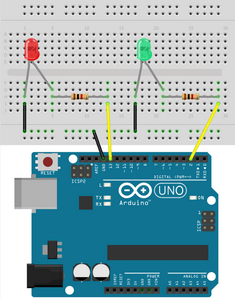
How to wire up and control LEDs has been widely described elsewhere.
e.g. https://www.circuitbasics.com/how-to-control-leds-on-the-arduino/ which includes this convenient figure:
Note that this example will illuminate the Red LED when GPIO 13 is pulled low, and the green LED when GPIO 2 is pulled low.
NB Longer leg of each LED is anode, and connects to positive supply.
It is essential to choose GPIO pins which are not already allocated to another task.
The next part will describe the programming operations to blink the red LED.
Part 2 – Host Setup and Red_Blink Sketch
The host computer could be a Windows PC, a Linux (e.g. Ubuntu) PC or an Apple MAC. The only significant differences is the different directory (folder) naming and forward slash versus back slash conventions used by Windows, and something like /home/ versus something like C:\user\. The following illustration is from Ubuntu, but it is assumed the reader can ‘translate’ to the equivalent situation, if they are using Windows or Apple.
For clarity, this topic now introduces a convenient directory structure of the whole project.
Assuming you are user dave, then create a directory for all DroneBot related sketches, with full read/write/execute permissions at a convenient point in the directory structure. e.g.:
/home/dave/Arduino/sketches/DroneBot
In that directory, create a sub-directory Crazy_Blinks which will hold all (three) of the sketches associated with the CRAZY_BLINK projects.
---------------------------------
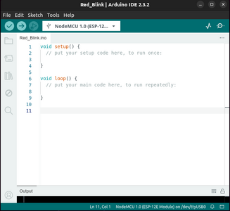
Start the Arduino 2.x.x IDE, beginning at the menu File
File → New Sketch
This should create a blank sketch. Save it in the Crazy_Blinks directory by:
File →Save
Navigate to the new directory /home/dave/Arduino/sketches/DroneBot/CrazyBlinks
and type in the name of the first sketch, Red_Blink, and click the Save button
This should return to the blank sketch.
Ensure that the selected Board and Serial Port matches the microcontroller board.
-----------------------------------------------------------
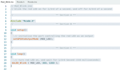
Edit the contents of a sketch to blink the red LED on for 1/3rd of a second, and off for 4/3rd of a second, by copy and pasting the code block below:
// Red_Blink.ino
// blink the red LED on for 1/3rd of a second, and off for 4/3rd of a second


// ------------------------------ ** Section A ** ---------------------------------------

// define the port output levels corresponding to on and off
#define LED_ON LOW
#define LED_OFF HIGH

// define GPIO port pin that controls the red LED
#define RED_LED 0


//--- ** Section B ** ---------------------------------------

void setup()
{
   // initialise the port controlling the red LED as an output
   pinMode (RED_LED, OUTPUT);

// ------------------------------ ** Section C ** -------------------------------------------

void loop()
{
   // turn red LED on, and wait for 1/3rd Second (333 milliseconds)
   digitalWrite (RED_LED, LED_ON);
   delay (333);
   // turn red LED off, and wait for 4/3rd Second (1333 milliseconds)
   digitalWrite (RED_LED, LED_OFF);
   delay (1333);
}
Edit the ‘zero’ in the line #define RED_LED 0 to match the number of the GPIO pin connected to the red LED part of the circuit.
Click the ‘Upload’ arrow icon, on the command line, and hopefully, the programme will correctly, compile, link , download to the board, and run, resulting in the red LED blinking on for 1/3rd of a second and off for 4/3 of a second.
If the programme is not operating correctly, then please try to fix it, before continuing.
----------------------------------------------------------
Red_Blink.ino Code Discussion
Before proceeding with the programme development, it may be helpful to consider the different sections of the script, from the compiler’s viewpoint.
The first two lines are comments describing the sketch.
Of course, comments are only intended for humans. The compiler ignores all comments, regardless of whether they are in a block, delimited by /* … */, or any part of a line after a double slash //
------------
Below this, 3 comment lines of the form // ----- ** Section A B C ** ----, have been included to emphasise three different sections of an Arduino sketch.
----------------------
From a compiler’s viewpoint, the comments do not exist, so just considering the 3 sections of ‘actual’ code:
Section B is strictly the ‘special’ function void setup () { … }, whose content limits are denoted by its outer pair of curly brackets.
Section C is strictly the ‘special’ function void loop () { … }, whose limits are denoted by its outer pair of curly brackets.
Section A in this simple sketch is illustrated as just the short section from the beginning of the sketch to immediately before the function void setup () {…} , but it would more accurate to describe it as all of the file that isn’t a part of either Section B void setup() {…} or part of Section C void loop() {…}
In fact, Section A also extends beyond the principal sketch file, to include all of the other source code files that make up the total programme.
The Arduino IDE is designed to shield the novice user from as much of the complexity as possible, so they can make rapid progress without getting bogged down in the details. But the compiling system is likely to have to work its way through hundreds, or thousands of files, to produce just one executable file, every time the user clicks the ‘upload’ button.
This discussion paper is not going to look any further into the complex details of the compiling and linking processes, but later, it will use the mechanisms (in a very simple way), to its advantage, to help merge two or more source files, which is the aim of this Fairy Tale project.
-------------------------------------------------------------------------------------
Having understood that an Arduino sketch divides into 3 sections, consider the aims and properties of each sections.
Section A
Section A is an Aladdin’s cave, which can contain an unlimited trove of treasures. In the file above, it only contains three handy definitions, but more generally, it can include variables, arrays, functions, classes and so on. And as already mentioned, there are 1000s of other files that the Arduino IDE may be automatically including in Section A.
Thus the compiler will use the expanded Section A source code to generate all of the processor code, memory allocations, and so on, that are requested. However, it is as though the compiler uses all of Section A to build a workshop, equips it with tools, materials, and so on, but there is no one in the workshop to operate it. So, without, some prompting from Sections B and/or C, much of Section A may never get ‘activated’.
Section B, which is function void setup() {…}, is the first sketch function to be called, and is intended to hold code needed to get the system ready for action. To use analogy of a aircraft pilot, this is the phase of flight from opening the outer door to the cockpit, entering the cockpit, through the pre-flight checklist, and warming up the engines. The function may access any of the resources in Section A, including executing functions defined in Section A. The function is only called once, and that is during the boot routine,
Section C function void loop() { … } is (repeatedly) called after void setup() { … } has completed. Many non-Arduino programs, especially those aimed at providing at never-ending continuous service, such as monitoring a sensor, are structured around a user defined loop that is called repeatedly. The Arduino sketch unusually provides this looping structure as a built in facility. Section C, like Section B, can also access all of the resources in Section A, including calling functions and so on.
------
Note: Beyond the scope of this discussion, it should be understood that some user programmes include user defined loops within void setup() { … } , so that the processor never exits from void setup() { … } and void loop() { … } is never invoked.
--------------------------------------------------------------------------------------------------------------
Part 3 – Green_Blink Sketch and Comparison of the Two Sketches
This is an appropriate time to return to the keyboard. The first sketch, Red_Blink.ino is able to blink the red LED in the specified manner. The next task is to create a second sketch which blinks the green LED at the rate specified for it, namely, on for 2 seconds, and off for 3 seconds.
To minimise the typing work, using the Arduino IDE with Red_Blink.ino sketch loaded:
-
Click File→ Save as
-
Check the directory the file will be saved in is Crazy_Blinks
-
Change the name the file will be saved as, to Green_Blink
-
Click the Save button
This should open a new Arduino IDE window, with a new sketch called Green_Blink.
----------------
(As a ‘double check’, use a operating system file manager (e.g Explorer with Windows) to view the current directory and file structure. It should have two sub-directories in Crazy_Blinks :
Green_Blink → Green_Blink.ino
…… / DroneBot / Crazy_Blinks / ---^
Red_Blink → Red_Blink.ino
----------------
However, the contents of the new file Green_Blink.ino, is presently the same as Red_Blink.ino
It needs to be edited, using the Arduino IDE window just opened, to match the Green_Blink requirement.
The changes are:
-
Update comments as appropriate (see listing below for suggestions)
-
-
Change #define RED_LED 0 to #define GREEN_LED 16
-
(assuming the GREEN_LED is connected to GPIO 16)
-
-
-
Change pinMode (RED_LED, OUTPUT); to pinMode (GREEN_LED, OUTPUT);
-
Change digitalWrite (RED_LED, LED_ON); to digitalWrite (GREEN_LED, LED_ON);
-
Change delay (333); to delay (2000);
-
Change digitalWrite (RED_LED, LED_OFF) to digitalWrite (GREEN_LED, LED_OFF)
-
Change delay (1333); to delay (3000);
Click the ‘Upload’ arrow icon, on the command line, and hopefully, the programme will correctly, compile, link , download to the board, and run, resulting in the green LED blinking on for 2 seconds and off for 3 seconds.
If the programme is not operating correctly, then please try to fix it, before continuing.
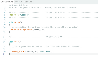
File Green_Blink.ino should now contain:
// Green_Blink.ino
// blink the green LED on for 2 seconds, and off for 3 seconds

// ------------------------- ** Section A ** ------------------------------------

// define the port output levels corresponding to on and off
#define LED_ON LOW
#define LED_OFF HIGH

// define GPIO port pin that controls the red LED
#define GREEN_LED 16

// ------------------------- ** Section B ** ------------------------------------

void setup()
{
   // initialise the port controlling the green LED as an output
   pinMode (GREEN_LED, OUTPUT);
}

// -------------------------- ** Section C ** ---------------------------------

void loop()
{
   // turn green LED on, and wait for 2 Seconds (2000 milliseconds)
   digitalWrite (GREEN_LED, LED_ON);
   delay (2000);
   // turn green LED off, and wait for 3 Seconds (3000 milliseconds)
   digitalWrite (GREEN_LED, LED_OFF);
   delay (3000);
}
Now have the microcontroller fully wired for both LEDs, and two independent sketches, each of can correctly drive their respective LED, but the LEDs cannot be run simultaneously.
Furthermore, each sketch has a different void setup() { …. } and void loop { …. } function, which would clash, if they were simply copied and pasted together.
For a simple programme like this, most programmers might simply copy and paste bits from the two sketches, to create a new sketch, adapting it as they go. However, let’s pretend that both sketches are much longer and complex, so that changing them in this ad hoc manner was likely to introduce a lot more bugs.
Are there methods of making the changes more incremental, and also being able to test the incremental changes without introducing new problems?
There isn’t a single ‘one-size fits all’ answer, but maybe there is a toolbox of tricks that can be applied.
Start by comparing the two sketches, and identify areas that they match, and areas that they differ. Then, look more carefully at the areas in which they differ, and further identify which ones will cause a ‘clash’ and which ones can be copied and pasted, so that they happily live side-by-side, without interfering which each other.
---
For convenience, use the Sections A, B and C split discussed previously, so that the comparison is Green_BLINK Section A, with Red_Blink Section A, and so on.
Initially, ignore the comments, as they can be tidied up later, and they do not affect the compiler.
Section A
#define ON and #define OFF are identical
#define RED_LED and #define GREEN_LED are different, but do not affect each other
So all of the code lines of both Section As are ‘mutually’ compatible
Section B
The two pinMode() functions have different parameters, but do not affect each other
So all of the code lines of both Section Bs are ‘mutually’ compatible
Section C
The digitalWrite () functions have different parameters, but do not affect each other
The delay() functions look more troublesome, as the timings are different, and they effectively have the processor ‘running on the spot’ , halting it’s progress for significant periods of time
---------------------
In this particular case, the two files are very short, so it is easy to follow any changes, but assuming they were more complicated, it can help to split each file into two or more separate files, so that the elements that are presenting a problem are brought to the forefront, whilst the rest of the (trouble-free) code is hidden. To do this, two empty files will be created in the same directory as the sketch file, and then parts of the sketch file will be copied into these new files. This process will first be applied to Red_Blink.ino, and then repeated for Green_Blink.ino. The modified Red_Blink.ino and Green_Blink.ino files, will then be tested to ensure they are still functional.
-----------------------------
Note that in each case, the code is being moved to two files to match the usual approach with C and C++, in which “.h” (or “.hpp”) files, known as header files, (mainly) contain information for the compiler, whilst “.cpp” (“.c”) files contain the ‘main’ code.
However, empirically, it seems the ‘.cpp’ file must be named ‘.ino.’ to ensure that the Arduino defined types are ‘known’ to the compiler.
-----------------------------
Part 4 – Splitting Red_Blink.ino into three files
This process is itself divided into parts, with tests after each part. This is excessively cautious for this simple example, but shows the principle that could be adopted for a more complex example.
- Create two empty files, Rcode.h and Rcode.ino, in the Red_Blink directory, which already contains Red_Blink.ino .
- Open Red_Blink.ino in an Arduino IDE window.
-
- The three files should be listed as Tabs
- Perform the following changes
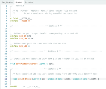
- To Rcode.h add the following lines:
// Rcode.h
// NB #ifndef→ #define→ #endif lines ensure file content
// is only read once, during compilation operation
#ifndef __RCODE_H__
#define __RCODE_H__
// ----------------------- ** Section A ** -----------------------------
// ---------------------- ** Section B ** ------------------------------
// ---------------------- ** Section C ** ------------------------------
#endif // __RCODE_H__
-
-
Note the #ifndef. #define & #endif lines containing __RCODE_H__, is a standard construction to ‘hide’ the contents of the file from the compiler, if the file is accidentally read more than once in the same compile operation
-
-
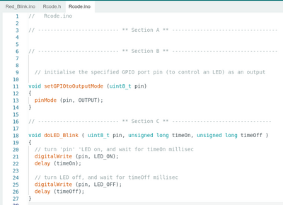
- To Rcode.ino add the following lines:
// Rcode.ino
// -------------------------- ** Section A ** ----------------------------------
// -------------------------- ** Section B ** ----------------------------------
// -------------------------- ** Section C ** ----------------------------------
- Section A of Red_Blink.ino :
-
- Analysis: This Section only consists of #define definitions, which are suitable for transfer to Rcode.h file, because they do not directly create any code for the processor
- LED_ON and LED_OFF, are identical for both Red_Blink and Green_Blink, so may move to shared Rcode.h file (only need one instance of these lines in the file)
- RED_LED is unique to Red_Blink, that does it clash with anything in Green_Blink, so may move to shared Rcode.h file
-
- Action: Move all of Red_Blink.ino Section A contents to Rcode.h
-
-
- (i.e. from “// define the port …” to end of section A” to Rcode.h
-
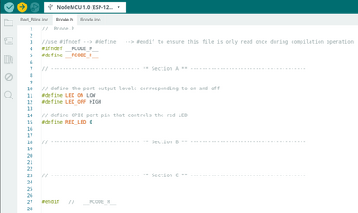
Rcode.h is now:
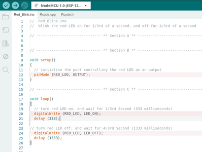
And Red_Blink.ino is now:
Try operating the Arduino IDE ‘Upload’ Arrow button. It should start to compile the project, but fail with 4 errors, including “error: 'RED_LED' was not declared in this scope”
This is to be expected, as the “#define RED_LED 0”, has been moved to Rcode.h, but the compiler didn’t read Rcode.h..
To overcome this, add the line #include "Rcode.h" to the file Red_Blink.ino, in the Section A area, so that Red_Blink.ino becomes:
/ Red_Blink.ino
// blink the red LED on for 1/3rd of a second, and off for 4/3rd of a second

// -------------------------- ** Section A ** ------------------------------------

#include "Rcode.h"
// --------------------------- ** Section B ** -----------------------------------

void setup()
{
   // initialise the port controlling the red LED as an output
   pinMode (RED_LED, OUTPUT);
}

// ------------------------- ** Section C ** -------------------------------------

void loop()
{
   // turn red LED on, and wait for 1/3rd Second (333 milliseconds)
   digitalWrite (RED_LED, LED_ON);
   delay (333);
   // turn red LED off, and wait for 4/3rd Second (1333 milliseconds)
   digitalWrite (RED_LED, LED_OFF);
   delay (1333);
}
Again, try operating the Arduino IDE ‘Upload’ Arrow button. This time, it should compile, without error, and continue to upload the new, finally resulting with the red LED flashing at the specified rate, showing that the changes have not introduced any new bugs.
The #include ”Rcode.h” addition forces the compiler to insert the whole contents of the specified file into the overall text, at that point, so that from the compiler viewpoint, the definitions are now effectively in the same position as they were before the cutting and pasting.
--------------------------------
Sections B and C each consist of function, whose name and invocation are part of the Arduino IDE operating system. The final project can only have a single void setup() {…} function and a single void loop () { ….} function, whilst Red_Blink.ino and Green_Blink.ino each have one of these functions, so it will be necessary to coalesce the functionality of the two setup functions into one function, and the two loop functions into one function.
For this example, there is only a very small amount of code, but there will often be much more, so it can be helpful to ‘package’ it into one or more functions, so that setup and loop functions look a lot simpler and not cluttered with the details. Furthermore, the intention of the code can become clearer, if the names of the functions reflect what they achieve, rather than the details of how they achievement is accomplished.
The next parts demonstrate some of the points just discussed.
----------------------------
-
Insert the following function prototype into Section B of Rcode.h
// initialise the specified GPIO port pin (to control an LED) as an output

void setGPIOtoOutputMode (uint8_t pin);
-
Insert the following function definition into Section B of Rcode.ino
// initialise specified GPIO port pin (to control an LED) as OUTPUT

void setGPIOtoOutputMode (uint8_t pin)
{
  pinMode (pin, OUTPUT);
}
-
Edit Section B of Red_Blink.ino by:
-
Remove
pinMode (RED_LED, OUTPUT);
-
Add
setGPIOtoOutputMode (RED_LED);
-
--------------------------
Note the result of the last three edits is to move the ‘detail’ code into a new function, which is defined in code.h plus Rcode.ino, and then call the new function in Red_Blink, instead of calling the ‘detail’ code directly. The next section similarly creates a new function to blink an LED, and the ‘detail’ code in Red_Blink.ino is replaced by a single function call.
----------------------------------------------
-
Insert the following function prototype into Section C of Rcode.h
	// turn specified LED on; wait timeOn msec; turn LED Off; wait timeOff msec

	void doLED_Blink (uint8_t pin, unsigned long timeOn, unsigned long timeOff);
-
Insert the following function definition into Section C of Rcode.ino
// -------------------------- ** Section C ** --------------------------------

void doLED_Blink ( uint8_t pin, unsigned long timeOn, unsigned long timeOff )
{
  // turn 'pin' 'LED on, and wait for timeOn millisec
  digitalWrite (pin, LED_ON);
  delay (timeOn);

  // turn LED off, and wait for timeOff millisec
  digitalWrite (pin, LED_OFF);
  delay (timeOff);
}
-
Edit Section C of Red_Blink.ino by:
-
Remove:
  digitalWrite (RED_LED, LED_ON);
   delay (333);
   // turn red LED off, and wait for 4/3rd Second (1333 milliseconds)
   digitalWrite (RED_LED, LED_OFF);
   delay (1333);
-
Add:
doLED_Blink ( RED_LED, 333, 1333 );
------------------------------------------------------
Try operating the Arduino IDE ‘Upload’ Arrow button. It should compile, without error, and continue to upload the new, finally resulting with the red LED flashing at the specified rate, showing that the changes have not introduced any new bugs.
As a check, the three files should be:
Red_Blink.ino
Rcode.h
Rcode.ino
Part 5 - Splitting Green_Blink.ino into three files
In most practical situations, the second file (Green_Blink.ino), would be completely different. However, for this demonstration, it is virtually identical, except that the LED is green, timings are on for 2000 millisecs, and off for 3000 millisecs.
If the above procedures, etc. are novel,as an exercise, it is advised to follow the same procedure as detailed in Part 4 above, making the changes and checking the modified project compiles at each stage.
Name the two new files Gcode.h and Gcode.ino, and change all occurrences of Rcode to GCode, in the three files.
Try operating the Arduino IDE ‘Upload’ Arrow button. This time, it should compile, without error, and continue to upload the new, finally resulting with the green LED flashing at the specified rate, showing that the changes have not introduced any new bugs.
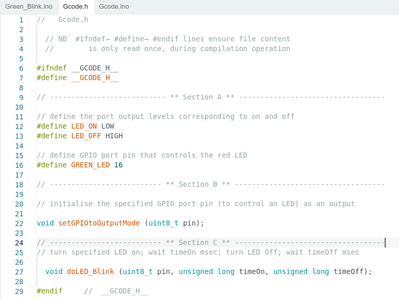
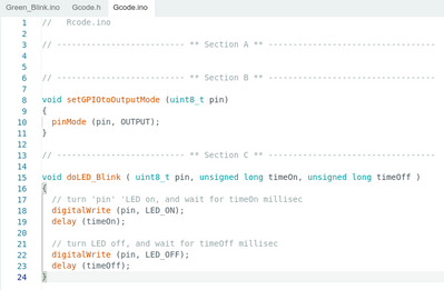
The three files should finally be as follows:
Green_Blink.ino
Gcode.h
Gcode.ino
@davee Here is another approach. This is the technicians solution, Dave's is the engineers solution. Both work, but one will get done in your lifetime.
#include <Arduino.h>

void setup() {
  setup1();
  setup2();
}

void loop() {
  loop1();
  loop2();
}

void setup1(){
  Serial.begin(115200);  // Remember to set Serial monitor to 115200 as well
  while (!Serial && (millis() < 5000)) ;  // Wait up to 5 secs for the Serial device to be ready
  Serial.println("setup1 done");
}

void setup2() {
  Serial.begin(115200);  // Remember to set Serial monitor to 115200 as well
  while (!Serial && (millis() < 5000)) ;  // Wait up to 5 secs for the Serial device to be ready
  Serial.println("setup2 done");
}

void loop1(){
  Serial.println("loop 1");
  delay(1000);
}

void loop2() {
  Serial.println("loop 2");
  delay(1000);
}
First computer 1959. Retired from my own computer company 2004.
Hardware - Expert in 1401, and 360, fairly knowledge in PC plus numerous MPU's and MCU's
Major Languages - Machine language, 360 Macro Assembler, Intel Assembler, PL/I and PL1, Pascal, Basic, C plus numerous job control and scripting languages.
My personal scorecard is now 1 PC hardware fix (circa 1982), 1 open source fix (at age 82), and 2 zero day bugs in a major OS.
Part 6 - Creating the Combined Project File
The two sub projects Red_Blink and Green_Blink, now have very simple main project files (Red_Blink.ino and Green_Blink.ino).
They also have very similar xCode.h and xCode.ino files, albeit that is partly due to the simplified project design.
In most cases, the equivalents of RCode.h and Gcode.h, plus the equivalents of Rcode.ino and Gcode.ino, would have more differences. But hopefully, the split will demonstrate which lines are duplicates, and which can be integrated into the same file, without causing any conflicts.
Also, in many projects, the processing will take the form of gather data from sensor from the first sub-project (Rcode.ino) and send processed commands, based on the incoming data, to the actuator in the second sub-project (Gcode.ino). This results in a very simple loop construction in the main project (x_Blink.ino)
In this particular project, the first ‘attempt’ will demonstrate this approach. It will result in both LEDs blinking, with the correct timing, but the LED operations will be sequential, not in parallel.
The second part of this phase, in Part 7, will involve changing the programme to provide the correct operation. This task will be much simpler, because the ‘detail’ code has been separated into the xCode.y files, leaving the main project file z_Blink.ino relatively simple and uncluttered.
-----------------------
The two sub-projects Red_blink and Green Blink are now useful test sets for any future changes, so we wil leave them unchanged at this point, and build the combined project in a new project, based on a copy of Red_Blink project, plus parts of Green_Blink.
-
Starting in Crazy_Blinks folder, Copy Red_Blink Folder and its contents to RG_Blink, also located in Crazy_Blinks
-
Rename files in RG_Blink as follows:
-
Rcode.h → RGcode.h
-
Rcode.ino → RGcode.ino
-
Red_Blink.ino → RG_Blink.ino
-
-
Open RG_Blink.ino in Arduino IDE
-
Edits to RG_Blink.ino are:
-
// Red_Blink.ino → // RG_Blink.ino
-
#include "Rcode.h" → #include "RGcode.h"
-
-
Edits to RGcode.h are:
-
// Rcode.h → // RGcode.h
-
RCODE_H → RGCODE_H (3 instances)
-
-
Edits to RGcode.ino are:
-
// Rcode.ino → // RGcode.ino
-
-
Select board and serial port, as this is a new project.
Try operating the Arduino IDE ‘Upload’ Arrow button. This time, it should compile, without error, and continue to upload the new, finally resulting with the red LED flashing at the specified rate, showing that the changes have not introduced any new bugs.
---------------------------------------------------------------
Now compare each of the three files in RG_Blink project, with the corresponding file in the Green_Blink project, and transfer the extra code needed
Gcode.h compare to RGcode.h
-
Only one line of code is ‘missing’ - Namely #define GREEN_LED 16
-
Adding this line will not affect the RED_LED code, so simply copy it.
-
-
Action:
-
Copy part of Section A in Gcode.h to Section A of RGcode.h
-
-
// define GPIO port pin that controls the red LED

#define GREEN_LED 16
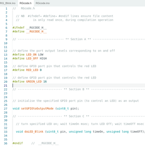
RG_Code.h is now:
Gcode.ino compare to RGcode.ino
-
Files are essentially identical … nothing to do
Green_Blink.ino compare to RG_Blink.ino
-
Section B: In void setup() { …. } :
-
Copy GREEN_LED initialisation code in to RG_Blink.ino i.e.
-
// initialise the port controlling the green LED as an output

setGPIOtoOutputMode (GREEN_LED);
-
Section C: In void loop() { ….}
-
Copy doLED_Blink code for green LED in to RG_Blink.ino i.e.
-
// turn green LED on, and wait for 2 Seconds (2000 milliseconds)

doLED_Blink ( GREEN_LED, 2000, 3000 );
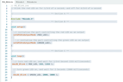
RG_Blink.ino is now:
Try operating the Arduino IDE ‘Upload’ Arrow button in the RG_Blink project. This time, it should compile, without error, and continue to upload the new, finally resulting with the red LED doing 1 blink, then the green LED doing 1 Blink, then repeating the sequence, each at their specified timing.
---------------------------------
As mentioned above, in many circumstances, this sequential processing is required, and the prototype project is complete.
However, in other cases, including this example, the two or more processes must appear to occur in parallel, and a more complex timing arrangement than the string of delay() functions is required.
Part 7 - Parallel Operation of the Two LEDs
At present, the program effectively ‘stops thinking’ at each delay() function call, for the specified number of milliseconds. Instead, the programme needs to appear to process instructions for both LEDs in parallel, without the operations of one LED, such as during a delay(); function call, preventing the other LED being switched on or off, at the appropriate time.
One technique to simulate a parallel processing operation. This might be achieved, by comparing the time that the next change is required, with the current time, and only perform the next action when the current time matches (or exceeds) the next change time. As there are no delay(); statements to monopolise the processor, the system can check the time as frequently as necessary.
--------
Note: The Arduino function millis() conveniently returns the time in milliseconds since the programme started.
e.g.
unsigned long progRunTime = millis();
--------
To further develop this principle, with minimal complexity, return to the Red_Blink code to initially implement it for just one LED.
The present function call in the loop() {….}, is
doLED_Blink(RED_LED, 333, 1333);
The first time it is called, the LED will be turned on, and the time for switch off can be recorded. For subsequent calls, the present time can be compared to the time to switch it off, which is given by the expression
Time to switch off LED = (time it was switched on) + (on time).
This logic can then be extended to sequentially switch on for time timeOn, and off for timeOff
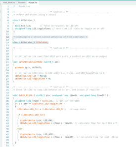
Status variables needed are conveniently defined using a struct:
// define LED status using a struct

struct LEDstatus_t
{
  bool LED_lit;				// false corresponds to LED off
  unsigned long LED_toggleTime;	// next time LED state to toggle on or off
};

// instantiate a struct called LEDstatus of type LEDstatus_t

struct LEDstatus_t LEDstatus;

Also, to ensure the struct starts with the correct values at time zero, assign those values in the function void setGPIOtoOutputMode (uint8_t pin) which is called from void setup(); {..} by adding two value assignments:

// initialise LEDstatus to LED unlit i.e. false, and LED_toggleTime to 0
LEDstatus.LED_lit = false;
LEDstatus.LED_toggleTime = 0;
Actions:
-
Add to Section A of Rcode.ino
// define LED status using a struct

{
  bool LED_lit;				// false corresponds to LED off
  unsigned long LED_toggleTime;	// next time LED state to toggle on or off
};

// instantiate a struct called LEDstatus of type LEDstatus_t

struct LEDstatus_t LEDstatus;
-
Add assignments in setGPIOtoOutputMode function, in Section B of Rcode.ino
// initialise LEDstatus to LED unlit i.e. false, and LED_toggleTime to 0

LEDstatus.LED_lit = false;
LEDstatus.LED_toggleTime = 0;
-
Replace do_LED_Blink code in Section C of Rcode.ino with:
// Check if time to swap LED between on or off, and action if required

void doLED_Blink ( uint8_t pin, unsigned long timeOn, unsigned long timeOff )
{
  unsigned long cTime = millis();  // get current time
  if ( cTime >= LEDstatus.LED_toggleTime )
  {
    LEDstatus.LED_lit = !LEDstatus.LED_lit;		// swap state

    if (LEDstatus.LED_lit)
    {
      digitalWrite (pin, LED_ON);
      LEDstatus.LED_toggleTime = cTime +  timeOn;	// calculate time for next LED off
    }
    else
    {
      digitalWrite (pin, LED_OFF);
      LEDstatus.LED_toggleTime = cTime +  timeOff;	// calculate time for next LED on
    }
  }
}
Rcode.ino is now:
Try operating the Arduino IDE ‘Upload’ Arrow button. It should compile, without error, and continue to upload the new, finally resulting with the red LED flashing at the specified rate, showing that the changes have not introduced any new bugs.
---------------------------
Extend to an Array of LEDS
This code now achieves the same effect as the previous version, without delays. However, it is only suitable for 1 LED.
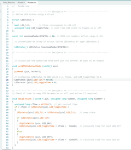
By extending the status variables to an array, it will be possible to have the status of two or more LEDs.
Each LED is presently addressed by the number of the GPIO pin which controls it. If we assume the maximum number of GPIO pins on any foreseeable microcontroller is 64, then this provides a convenient size for the array.
Although the Red_Blink uses only 1 LED, the programme can be extended and retested with the array.
Note, Because, it is inconvenient to initialise the array, set each affected GPIO status to default values of false and zero, when setting the pin to output in void setGPIOto OutputMode (uint8_t pin) {….}
Actions:
Edits to file Rcode.ino:
-
Change Section A of Gcode.ino by:
-
Replace
-
// instantiate a struct called LEDstatus of type LEDstatus_t

	struct LEDstatus_t LEDstatus;
-
with
const int maximumMumberOfGPIOs = 64; // GPIO pin numbers within range 0..63

	// instantiate an array of struct called LEDstatus of type LEDstatus_t

	LEDstatus_t LEDstatus [maximumMumberOfGPIOs];
-
In Section B of Rcode.ino
Change LEDstatus to an array element, addressed by pin in the body of setOutputMode (uint8_t pin){….}
       LEDstatus [pin].LED_on = false;
       LEDstatus [pin].LED_toggleTime = 0;
-
Do the following changes to Section C of Rcode.ino
Change LEDstatus.LED_lit to LEDstatus[pin].LED_lit // 3 instances
Change LEDstatus.toggleTime to LEDstatus[pin].toggleTime // 3 instances
------------------------------------
Rcode.ino should now be:
Try operating the Arduino IDE ‘Upload’ Arrow button. It should compile, without error, and continue to upload the new, finally resulting with the red LED flashing at the specified rate, showing that the changes have not introduced any new bugs.
Apply tested Rcode.ino to RGcode.ino
Having developed new code, for Rcode.ino, compare that with RGcode.ino, to migrate the changes.
Notice that the Rcode.ino contents can be directly copied in.
-----------------------------------------------
Action:
Apart from the top line comment, which indicates the filename, replace the entire contents of the RGcode.ini from the RG_Blink project with the corresponding entire contents Rcode.ino from the Red_Blink project.
Operate the Arduino IDE ‘Upload’ Arrow button, for the RGBlink project.
The project should compile, link and download, then execute the completed project, with both red and green LEDs blinking at the same time, with their specified respective on and off times.
The Fairy Tale has come true – The sketches are now happily married together - Mission accomplished!!!
Epilogue – extra notes and hints
For this example, the additional files were:
-
one .h file was added to hold ‘information’ lines of code, such as #define, and also to hold function prototypes
-
one .ino file was added to define functions and to define global variables that were private to those functions
In a more complex project, it may be helpful to have more than one extra .ino file, and they may be added as required. For example, there might be two different types of sensor, and one actuator, which could use 4 .ino files, one for each sensor, one for the actuator, and a fourth overall .ino file acting as a manager for the whole project.
Similarly, it may be convenient to have more than one .h file, for example, there could one corresponding to each extra .ino file. Remember that although .h files in the same Arduino project ‘tabbed’ if they are in the same project directory, they are only read by the compiler at compile time when they are referenced by an #include statement.
If you do not want to see a .h file tab in the IDE window, then it may be ‘hidden’ by moving the .h file to another folder, which might conveniently be a sub-folder in the project directory. The compiler can still be instructed to read the .h file, by adding the path to the #include statement.
Hi Dave, a good tutorial and I like the fact you introduced the concept of using multiple program files that are linked to be imported into the new main program. This is not usually found in the beginners tutorials but when attempting to go for one's first biggy then its easy to get into a horrible lengthy bunch of code that not so easy to trawl through.
Also your introduction to the drawbacks of using delay, and that blocking code is going to be problematic in any larger program is apt. A mention of millis is good, but embedded programs are often expected to run infinitum, a brief mention that the millis rollover consideration may need to be considered if the program is to run for an extended time, thus the warning a beginner that they may need to study this aspect in future would be apposite. (not suggesting that your tutorial should stray into the weeds on this)
I'm waffling so I best get the main point of why I penned this and that is to suggest the tutorial would be better presented as an included pdf file. I think this would both enable it to be better read, you would have more control as to its format and presentation, and the flow would not get interrupted by other posts such as the one that seems to blithely suggest all thats required is to copy all the chunks of code into one file (and a beginner may be fooled into thinking how simple it all is, usually to end up very disappointed). It would also better facilitate the user having a go at the coding as they could follow along with a printed version if they don't have multiple screens in their set up.
But well done, I hope the intended recipient does take just an hour or so to go through the process you elucidate, they will learn a lot from this tutorial.
@davee Hi Dave. Once again, thank you for your time and effort to break down the process for me (And hopefully many others) as I move toward a better understanding of what all beginners will need to move forward. I have read through all of the steps, and it seems doable for me, so off I go. Lately I’ve had less time to devote to my early learning (and screwups), but I intend to make more of an effort to start from scratch with your tutorial, and see how far I get. Good to know you’re out there, and I’ll talk to you soon. Bill
Hi @byron,
Thanks for your constructive thoughts, which are very much appreciated.
In terms of the technical points to include, I wasn't sure if I had the right overall balance. I wanted to discuss things which experienced programmers would take for granted, but I thought might not be so obvious to people coming from different backgrounds, knowing that Arduino 'culture' is to make otherwise complex systems accessible to newcomers. For example, I introduced the idea of breaking an Arduino script into three sections, the two functions loop and setup, plus 'The rest', because I became aware of more than 1 person putting executable-style code in 'The rest' area (with no calls to it from setup or loop), and wondering why it never did anything, except upsetting the compiler.
You are of course right to point out that embedded machines are often 'expected' to run forever, whilst millis() is said to rollover after about 50 days, which will be a problem for a substantial minority of projects. Arithmetic problems like underflow, overflow, mixing single and double precision, 8-bit vs 16-bit vs 32-bit integer formats, and so on, are well known, but have still managed to catch some people out, including the destruction of at least one satellite launch ( http://sunnyday.mit.edu/nasa-class/Ariane5-report.html).
I confess to not having considered it for my flashing LEDs programme, if only because the flashing LEDs are too boring to watch for 50 seconds ... even 5 seconds is a struggle! 😴 😴 😴 😴
So whilst I don't feel too bad about the omission, for this particular sermon, which is already too long, I think it is an important topic, and one that often gets overlooked ... apparently by rocket scientists as well as the rest of us mortals. Should it be the subject of another forum discussion paper? Will anybody read it?
As for simply providing a pdf, ironically that would have saved me several hours, but is it the right thing to do?
Because of its length, and the 1 hour limited time to edit scripts once they are posted, I didn't type it in directly, but instead wrote it in LibreOffice Writer, then copied it section by section, onto the forum, which wasn't much fun, but I thought this would be more immediate to the reader, whilst a humble pdf link would never get noticed, but perhaps I am mistaken, so I invite others to comment.
I agree that is useful to be able to print it out. Naively, I thought this was possible, but I now see there are issues, so perhaps a pdf as well would be the best solution?
Thanks once again for your insights.
Best wishes, Dave
@davee I strongly support the pdf idea. For newer folks who will need to read and re-read the 35ish screens of information with back references etc, a pdf is much preferred, and I always like to print out useful documents usually in colour 2 up 2 sided (4 logical pages per physical) as I can still read type that small.
I hope you still have the LibreOffice copies, because that will make it simple to produce the pdf. I think it should be a single PDF, unless you the author think there is a good reason to break it up into multiple pdfs. Breaking it up for posts makes sense though.
BTW, when the original issue came up I did merge the sketches, but I did it in a single setup and single loop as it was so trivial. I am glad to see you took the subject matter further and gave it the Dave treatment, it will be of most help to the intermediate folks. I wonder if a simpler condensed version would be better suited for absolute beginners like the OP?
I hope you enjoyed my little tongue-in-cheek post, apparently not all Brits did
First computer 1959. Retired from my own computer company 2004.
Hardware - Expert in 1401, and 360, fairly knowledge in PC plus numerous MPU's and MCU's
Major Languages - Machine language, 360 Macro Assembler, Intel Assembler, PL/I and PL1, Pascal, Basic, C plus numerous job control and scripting languages.
My personal scorecard is now 1 PC hardware fix (circa 1982), 1 open source fix (at age 82), and 2 zero day bugs in a major OS.
I also think a .pdf copy would be most helpful. I have been working on putting the post(s) back in a Libre document.
As for the actual content, EXCELLENT!
With your permission, I’d like to use this as a basis for a class or two on the subject in a STEM class I have been assisting in teaching on programming and MCU’s.
Thanks and regards,
Hi @lee-g,
I'll try to put a pdf up sometime tomorrow (UK time) ... hopefully I have it, but it was a 'handraulic' transfer, possibly with tweaks, so I need to check it.
Please feel free to use it ... no responsibility accepted for any goofs (AKA 'deliberate mistakes'), so check anything you present!
Best wishes, Dave
Thanks and no rush, our (next) class does not start for several weeks.
Appreciate all your work on this. (If for some reason you don't have a pdf copy, don't worry about it. We can "improvise"!)
Regards,
Lee
Hi @lee-g, @zander, @billinfl, @byron,
In reply to an "overwhelming" number of requests, I attach a pdf of this previously posted topic.
Or to be strictly accurate, a pdf that is meant to be the same basic content, with a few minor tweaks, hopefully improvements..
I apologise that the 'configuration control' between the versions has been non-existent, so you might find some new bugs as well, but hopefully it will be useful.
Best wishes, Dave
@davee Hi Dave. I finally got back on the project over the past few days. The PDF tutorial has been very helpful, and I feel like I've been doing pretty well, although I do spend way too much time correcting minor keystroke errors, (I don't know how to type, so that can't help), and looking for what's wrong and why something isn't working. I can stare at multiple pages for quite some time before realizing that a tiny error is the culprit, but I guess this type of "fun" is what I should expect at my level. Well, I could go on bellyaching, but for now, I have bigger fish to fry. And, as usual, I don't know how big of a fish I'm dealing with. I've made it all the way to page 22, (step 6), without having to bug you, but after so many do-overs and double-checks with this newest problem, I've given up trying to figure out why I can't get the LED timing to do what it's supposed to. (Green on for 2000, and off for 3000, and Red on for 333, and off for 1333). To be clear, both LED's do exactly what they're supposed to when I upload the sketches (Green_Blink and Red_Blink) one at a time, but now that I've combined them, (page 20), I'm getting totally wrong timing, specifically, green on for 5 seconds, and off for 2 seconds, as well as Red on for 7 seconds, and off for 1/3 second.(!!) I didn't ask for those times, but somehow it's decided to give me them anyway. I think I've said a bad word....a few times. I'm not sure how to proceed. Any ideas? Thanks much Dave! Bill

