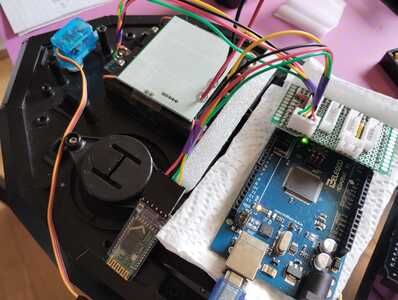
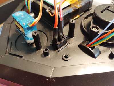
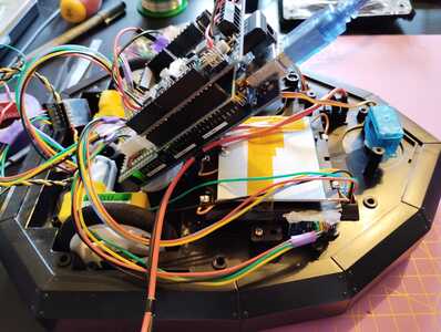
It worked perfectly fine so far. I was able to connect to my PlayStation Navigation Controller and added some simple commands. Next, I'll add the analog joystick to make it a bit smoother.
Here's a short demo:
I also had a closer look at the MPU6050, but it seems to not be of much use. I thought it had a compass or I could find out how many degrees the Dalek turned. But that seems to not be possible. I'll need a different sensor.
Current projects:
- Modding my Gameboy Advance SP
- Turning Dalek into robot
Finished projects:
- Talking plant monitor (ESP8266)
- Mail box monitor (ESP8266-01S)
Other devices:
- Raspberry Pi 4B 4GB running Home Assistant
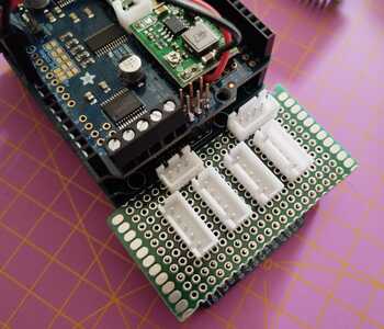
I ordered a few ToF I²C distance sensors to prevent collisions. So, I decided to redo the perfboard mini shield to add more JST sockets. This time, I'll use SMD resistors to save some space.
Here's the first idea how to place the sockets:
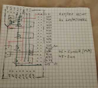
I even drew a small sketch for how to connect everything:
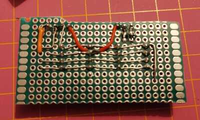
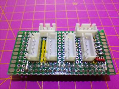
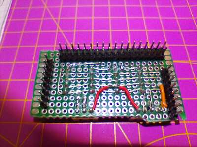
Here's the soldering so far, what's left are the connections for the shutdown pins, and the pins for plugging into the Arduino Mega:
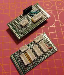
A small comparison of old and new board:
I think this is a good improvement.
Current projects:
- Modding my Gameboy Advance SP
- Turning Dalek into robot
Finished projects:
- Talking plant monitor (ESP8266)
- Mail box monitor (ESP8266-01S)
Other devices:
- Raspberry Pi 4B 4GB running Home Assistant
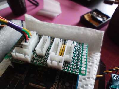
Here is the finished board, I'm using pins 34, 36, 38, and 40 for the enable/shutdown connection:
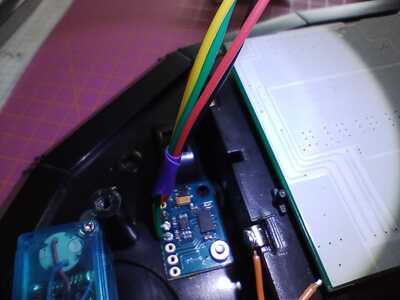
I also got my LSM303DLHC module, which I'll try to use as compass. I crimped a cable and soldered it to the module, plugging it into one of the I²C sockets:
It doesn't have a enable or shutdown pin, so pin 5 is left empty. It almost fits into the holes I drilled for the MPU6050, but I'll have to find a different location for it, because the magnet of the servo next to it interferes.
This aside, it works fine, when I keep it away from the servo. I also plugged in the HC05 module and it works perfectly:
I have to find a new way to hold the arduino in place, since the I²C sockets are in the way of the wirestrap I used before.
Next will be adding the ToF distance sensors and adding them to the code.
Current projects:
- Modding my Gameboy Advance SP
- Turning Dalek into robot
Finished projects:
- Talking plant monitor (ESP8266)
- Mail box monitor (ESP8266-01S)
Other devices:
- Raspberry Pi 4B 4GB running Home Assistant
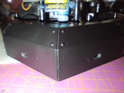
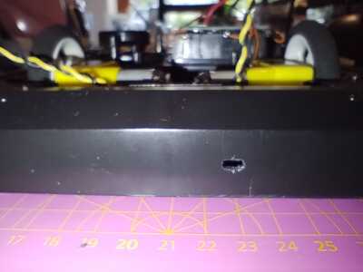
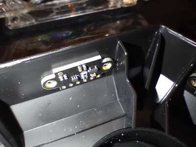
Another update! I finally decided how to install the ToF distance sensors. I drilled a three small holes in the front and rear, exactly the size of the sensors on the modules:
This modification is small enough to not disturb the overall look of the Dalek.
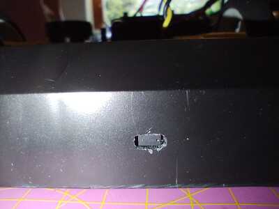
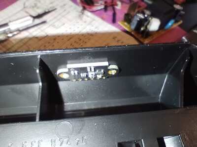
Here a look from inside. The fit is so tight that it holds without additional support:
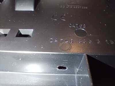
The rear sensor had to be placed with a bit side offset, since there's a rib in the middle. For the rear sensor, I also drilled a small hole for the cables:
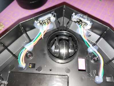
The front ones could be routed through the existing holes. After soldering the wires, I added a bit of hot glue to keep it safe:
I know I could have Daisy-chained them, but decided to keep the wiring separated, to stay flexible, and I need separate shutdown wires anyway, to set the I²C address during the setup function, since those modules don't have persistent configs.
Current projects:
- Modding my Gameboy Advance SP
- Turning Dalek into robot
Finished projects:
- Talking plant monitor (ESP8266)
- Mail box monitor (ESP8266-01S)
Other devices:
- Raspberry Pi 4B 4GB running Home Assistant
I had to move my projects away, since we had some guests, and I was distracted by some side-projects involving retro game consoles (creating a USB-C PD power supply for Nintendo 64, cleaning and taking care of the lithium batteries in a collection of handhelds, modding my Gameboy Advance SP). So I didn't have a lot of time to work on my Dalek. But still, I wanted to give a brief update.
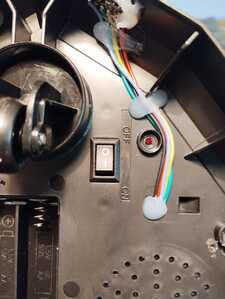
I found a power switch that fitted almost perfectly into the opening for the original switch, only had to scrape a tiny amount of plastic at the side:
I placed it in the positive cable from the BMS.
Also, I did a few test runs and modified my code to initialize the DoF sensors correctly and assign a unique ID to each. Sadly, the compass module seems to be defective, one axis always returns -4096. I might have to get a replacement, or live without. Here is my test setup with motors not connected:
There were no batteries inserted, and maybe I should rethink my cable management...
Current projects:
- Modding my Gameboy Advance SP
- Turning Dalek into robot
Finished projects:
- Talking plant monitor (ESP8266)
- Mail box monitor (ESP8266-01S)
Other devices:
- Raspberry Pi 4B 4GB running Home Assistant

