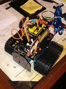
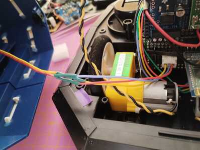
Here a short video of the servo in action:
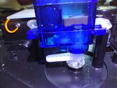
Screwed like this the servo axis sits exactly above the screw of the wheel. I just have to find a way to attach it to the front wheel - maybe some hot glue?
Looks like I should finally get a hot glue gun...
Current projects:
- Modding my Gameboy Advance SP
- Turning Dalek into robot
Finished projects:
- Talking plant monitor (ESP8266)
- Mail box monitor (ESP8266-01S)
Other devices:
- Raspberry Pi 4B 4GB running Home Assistant
@rommudoh Good start, but I assume it goes in both directions and can move very small amounts slowly.
I, too, am a hot glue fan, but I would add a piece on each side of the connection that I can remove if needed and hot glue them together. Some coupling mechanism with a grub screw on a flat, maybe, or two? The challenge will be to build something to hold the glue in place while it sets.
First computer 1959. Retired from my own computer company 2004.
Hardware - Expert in 1401, and 360, fairly knowledge in PC plus numerous MPU's and MCU's
Major Languages - Machine language, 360 Macro Assembler, Intel Assembler, PL/I and PL1, Pascal, Basic, C plus numerous job control and scripting languages.
Sure you can learn to be a programmer, it will take the same amount of time for me to learn to be a Doctor.
Yes, I should have made it turn the other way for that video...
Thank you for your input! I'll have a bit of time to think about it, since I can't work on this project for a bit.
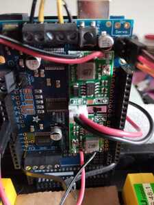
Btw, I refined the power connection by replacing it with a JST connector. Just had to scrape a bit of plastic off, but now it can't be inserted reversed and it is harder to get loose:
Current projects:
- Modding my Gameboy Advance SP
- Turning Dalek into robot
Finished projects:
- Talking plant monitor (ESP8266)
- Mail box monitor (ESP8266-01S)
Other devices:
- Raspberry Pi 4B 4GB running Home Assistant
Some updates!
I got myself a hot glue gun and started by glueing the servo to the front wheel:
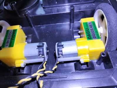
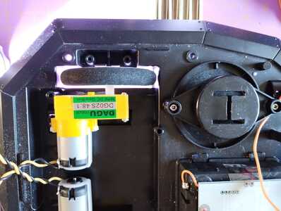
Next, I decided to glue the back motors in place, too, since the double sided tape started to loosen to fast:
As you can see, the wheels fit perfectly now!
After calibrating it anew, it drives an almost perfect square:
Next, I'll start adding the IR remote, maybe even a Bluetooth module.
Current projects:
- Modding my Gameboy Advance SP
- Turning Dalek into robot
Finished projects:
- Talking plant monitor (ESP8266)
- Mail box monitor (ESP8266-01S)
Other devices:
- Raspberry Pi 4B 4GB running Home Assistant
Are you using odometry to drive the box pattern?
I don't have any sensors connected, yet. The box pattern is done by pure math, after calibrating the timings. I assume a linear relation between motor speed and distance.
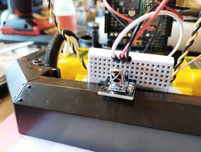
I now have added a simple IR receiver:
I programmed it to do basic commands: forward, backward, and 90° turns left or right. also two buttons to set speed and distance to slow or high.
It works very good, and decodes the signals almost every time even when the receiver is facing the opposite direction. I would've thought it worse.
Nevertheless, I already plan on replacing it with Bluetooth or WiFi, since I don't want to put a hole into the final case for the receiver. I'll already have to modify it for the planned collision sensors.
Here a short demonstration:
Current projects:
- Modding my Gameboy Advance SP
- Turning Dalek into robot
Finished projects:
- Talking plant monitor (ESP8266)
- Mail box monitor (ESP8266-01S)
Other devices:
- Raspberry Pi 4B 4GB running Home Assistant
@rommudoh Looks great! However, you might consider using bluetooth of wiFi instead as you would have to expose the IR though the Dalek cover for it to receive the IR signal..and as I remember you stating you didn't want to mar up the Dalek as little as possible. I used Wifi on my Robot tank :
I removed the bluetooth module and mounted a esp8266MCU on top of the robot for Wifi:
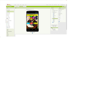
Then designed my own app using MIT App Inventor for my Android phone :
Works very well..however the wifi range is limited in the house.. so that's a problem I'll be working on to see if I can use WiFi Access Point on the phone..
regards,
LouisR
LouisR
Nevertheless, I already plan on replacing it with Bluetooth or WiFi, since I don't want to put a hole into the final case for the receiver.
Indeed, that is something well worth learning, communication between your projects and a PC or smart phone. This would mean learning how to program an interface on a PC or smart phone.
Other ways of detecting a collision, which really shouldn't be an issue for remote control, might be to monitor the motor currents (or free wheel not turning) or one of those little accelerometer modules.
So, my Bluetooth module arrived. But for today, I only did a bit of soldering to prepare for it.
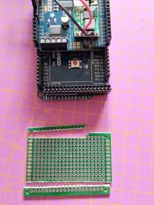
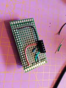
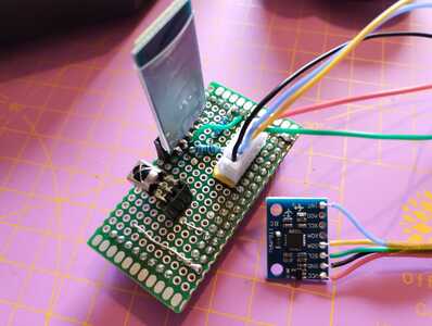
Since I use an Arduino Mega, there is a bit of unused space at the bottom. Conveniently, this is where the additional UART pins are, and which I want to use for the module. So, I cut a small perfboard to fit there and plug into the Arduino:
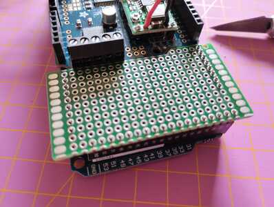
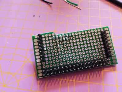
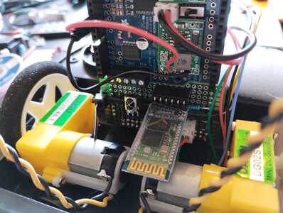
After soldering the pins and the headers for the module, it fits nicely:
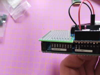
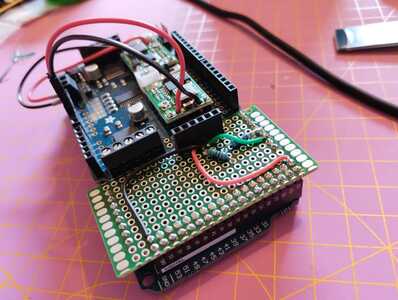
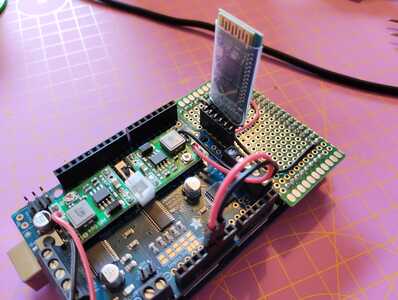
Finished assembly:
Now I can change the programming tomorrow or this weekend 🙂
Current projects:
- Modding my Gameboy Advance SP
- Turning Dalek into robot
Finished projects:
- Talking plant monitor (ESP8266)
- Mail box monitor (ESP8266-01S)
Other devices:
- Raspberry Pi 4B 4GB running Home Assistant
I just couldn't leave it like that, had to change it again.
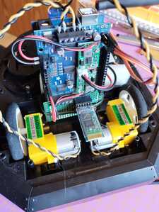
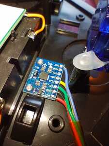
I want to keep the IR in addition to the Bluetooth module, so I added a 3 pin socket. Also, I added a 5 pin JST connector to plug in a MPU6050 - the first sensor I'll be using yay!
For mounting the MPU6050, I drilled two small holes and screwed it into place using M2 screws:
This should keep it safe.
Current projects:
- Modding my Gameboy Advance SP
- Turning Dalek into robot
Finished projects:
- Talking plant monitor (ESP8266)
- Mail box monitor (ESP8266-01S)
Other devices:
- Raspberry Pi 4B 4GB running Home Assistant
In the end, I gave IR up for now. At first I confused VCC and GND, killing one of my two IR receivers, and now I can't get the other one working correctly. But using the Bluetooth module works very fine. I changedbthe code to accept parameters to the commands, so I can specify how many degrees it should turn, or how far it should drive.
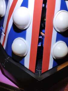
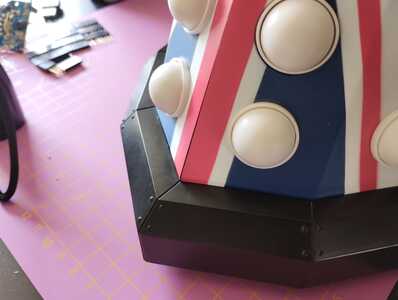
Next, I put the top case back onto the base, and realized that the servo for the steering wheel is a bit too high, so it either sits on the servo, or a bit offset to the front:
Here a comparison with the top case at the side:
I removed the servo (hot glue is easily removable), and glued it back on without the servo arm that I had added to make it fit better but needing more space:
But sadly it still dosn't fit 🙁
Current projects:
- Modding my Gameboy Advance SP
- Turning Dalek into robot
Finished projects:
- Talking plant monitor (ESP8266)
- Mail box monitor (ESP8266-01S)
Other devices:
- Raspberry Pi 4B 4GB running Home Assistant
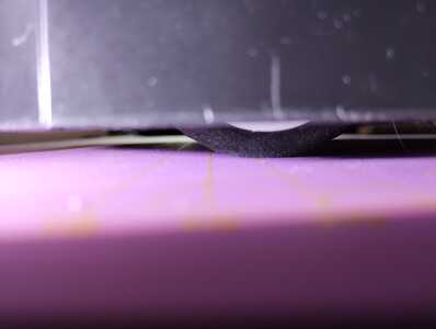
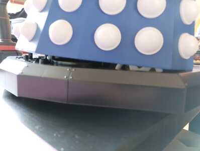
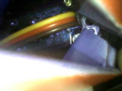
After fetching my laptop and USB mini-camera, I took a foto of the colliding parts. This time it isn't the vertical height of the servo, but the different angle - the front edge is just a bit too far in the front and collides with a horizontal bar of the top case:
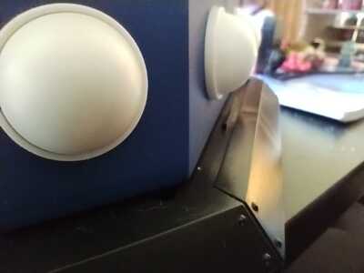
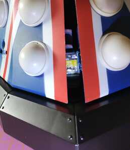
After identifying it, I could take a better foto with my mobile phone:
I'll have to find a better fitting servo, or try to remove a part of the horizontal bar of the case.
Current projects:
- Modding my Gameboy Advance SP
- Turning Dalek into robot
Finished projects:
- Talking plant monitor (ESP8266)
- Mail box monitor (ESP8266-01S)
Other devices:
- Raspberry Pi 4B 4GB running Home Assistant
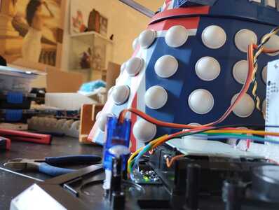
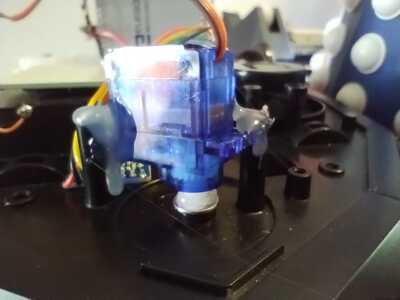
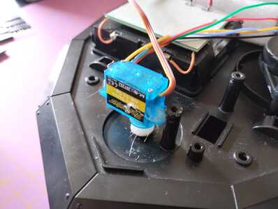
Small update. I received a smaller servo, and it fits nicely:
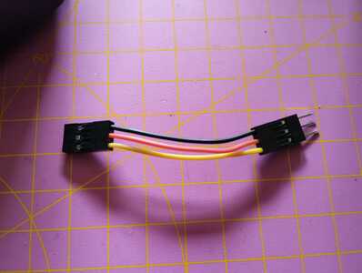
The cable was a bit too short, so I crimped myself an extension cable.
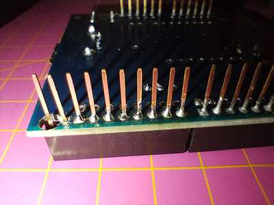
I also got my USB host shield for adding a Bluetooth dongle for HID devices like a PS3 controller. I modified it by replacing the 8-pin header with a 10-pin header after drilling a small hole, to be able to put it between the Arduino and the motor shield, since the latter uses the SDA/SCL from that position:
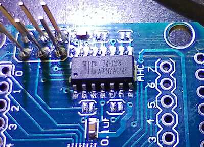
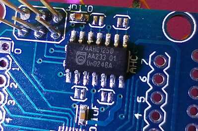
I noticed too late that the USB host shield isn't usable as it came. It has a 74HC125 instead of a 74AHC125, and this makes it fail to recognize attached devices. Also, it seems to feed a higher voltage back into the 3.3V power circuit (around 3.8V), so I'll wait until I get a replacement IC and swap it. I don't want to damage my Arduino.
Also, I added a connector for the 3-wire cable leading into the head part and controlling the LEDs. The eye LED is connected to pin 46, which is PWM capable.
It took a while until I figured out why PWM didn't work when the Servo was attached and why the steering servo jittered when trying to use PWM: It is wired to timer 5, which is the first timer that gets used by the Arduino Servo library on the Arduino Mega. There sadly is no way to tell the library not to mess with it, so I forked the Servo library and removed timer 5 from the list of usable timers ( https://github.com/oenone/Servo ). Maybe I'll clean it up sometime and try to get it merged into the official library.
Nothing else to show, yet, since lots of time wasted in trying to get the USB host shield working. Until I receive the proper IC, I'll try to integrate the MPU6050 somehow.
Current projects:
- Modding my Gameboy Advance SP
- Turning Dalek into robot
Finished projects:
- Talking plant monitor (ESP8266)
- Mail box monitor (ESP8266-01S)
Other devices:
- Raspberry Pi 4B 4GB running Home Assistant
Another small update. I got a full refund on the nonworking USB Host Shield, and my replacement ICs arrived. Here is the result of replacing it:
(I used my chisel head and 1mm leadfree solder, worked suprisingly well)
Didn't have time to test it, yet, but the overvoltage issue is gone now.
Current projects:
- Modding my Gameboy Advance SP
- Turning Dalek into robot
Finished projects:
- Talking plant monitor (ESP8266)
- Mail box monitor (ESP8266-01S)
Other devices:
- Raspberry Pi 4B 4GB running Home Assistant

