I have started a project to use a DC motor to adjust my solar panels. I am using a IBT_2 H bridge to control the motor. The issue that I am having is that I can not figure out how to incorporate directional buttons into the code to move the motor in either direction. For some reason I am not understanding how to accomplish this with python.
The more information you provide (such as the code you are talking about and if it is running on an Arduino or Raspberry Pi ) the more likely you will get useful feedback.
http://www.hessmer.org/blog/2013/12/28/ibt-2-h-bridge-with-arduino/
Thank you robotBuilder for that assistance. I am using a Raspberry Pi Pico W and using Thonny.
@gomermil When you reply use the reply button on the post you are replying to. If you haven't already, go to the help --> above recent posts and learn how to post the code you are using. You may want to also give a little more info re hardware such as tracking hardware, is it purchased or homemade.
First computer 1959. Retired from my own computer company 2004.
Hardware - Expert in 1401, and 360, fairly knowledge in PC plus numerous MPU's and MCU's
Major Languages - Machine language, 360 Macro Assembler, Intel Assembler, PL/I and PL1, Pascal, Basic, C plus numerous job control and scripting languages.
Sure you can learn to be a programmer, it will take the same amount of time for me to learn to be a Doctor.
@robotbuilder I am using the code from the link that you gave me but I am having problems getting it to work. Do you have any suggestions on how to repair it. It tells me that line 31 will not compile. If you could assist with this it would be great thank you.
You'll need to change the "<" to "<". The amperdsanded form is necessary for it to be represented properly in the article but the Arduino uses the < sign.
Anything seems possible when you don't know what you're talking about.
So I have attempted to get this to work on my pico W but with no avail. I changed the sensor pin to pin 31 on the pico, but my lack of programming skills are keeping me from getting this to work still. Can anyone assist me on this please?
Hi @gomermil,
I wondered if you realised that pin 31 of a Pico W is GPIO26 or ADC0. The software will use the latter numbers, probably the '0' from ADC, assuming you are using it to measure the voltage from the potentiometer.
I didn't see a "GPIO31" or "ADC31" pin, so the software would probably reject it, as there is no such pin.
I haven't worked with the Pico family, but if I was in your position I would look for a few simple Pico 'breadboard' projects using potentiometers and switches that are well explained, and try them out, to get some practical experience and knowledge, before getting into the more complex project you wish to achieve.
Best wishes, Dave
@gomermil FYI @davee Change the pin to D26. It's Digital Pin 26 hosted on board in 31.
A common way to do this is as follows. The CONSTANT D26 is built-in, as well as all the other Digital Pins plus all kinds of constants for the rest of the pins. This is true for any of the boards we work with AFAIK.
const pin_size_t myPinIn = D26;

void setup() {
  pinMode(myPinIn, mode);
}
First computer 1959. Retired from my own computer company 2004.
Hardware - Expert in 1401, and 360, fairly knowledge in PC plus numerous MPU's and MCU's
Major Languages - Machine language, 360 Macro Assembler, Intel Assembler, PL/I and PL1, Pascal, Basic, C plus numerous job control and scripting languages.
Sure you can learn to be a programmer, it will take the same amount of time for me to learn to be a Doctor.
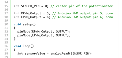
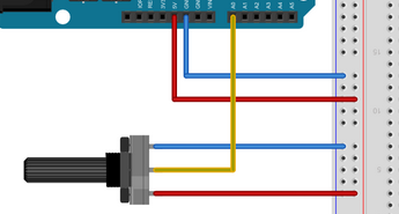
@gomermil, unfortunately you have not really provided enough information about what you have done to enable anyone to provide more than speculative advice. Hence my speculative suggestion was based on clips from the hessmer reference from @robotbuilder:
and
which show that the 'sensor' pin '0' for the Arduino, is measuring the potentiometer wiper voltage and uses an analog ADC input pin '0', not a digital input.
Looking at pin 31 on the Pi Zero W, shows it can be configured to any one of three different roles:
clipped from https://www.raspberrypi.com/documentation/microcontrollers/raspberry-pi-pico.html
Hence, if it is configured as a
- digital input or output pin it would be GP26 ... which might be written as "D26" for certain compilers/libraries as Ron suggests
- analogue input, such as would be required to read a potentiometer output voltage, it would ADC0 ... which might be programmed as simply '0' for certain compilers/libraries. The program clip above shows SENSOR_PIN to be of 'int' type, so that must be a simple integer number, such as 0.
Sorry, I haven't used this particular board or library, and this might vary if you move from Arduino to Python environment, so you will need to check the appropriate documentation, for the exact syntax.
Hope this helps. Best wishes, Dave
@davee Thank you for all your assistance, Dave, you have helped a lot. My biggest issue is that I started to learn Python and know nothing about Arduino. You are correct though I do need to do more learning before I attempt to do this big project.
@zander Thanks for the help. I am going to have to do more learning before anything else that's for sure.
Hi @gomermil,
We are all learning all the time .. and some of us have been playing with this stuff for a long time already! The trick is not to try to do massive jumps ... start with something easy and build it up a step at a time.
That way, if you go from a stage you understood and works, to a new stage that doesn't work, then you can be pretty confident the problem is going to be related to the change.
At the beginning, even the smallest and 'most obvious' errors, will not be obvious, and typically will totally 'break' whatever you are trying to achieve. The good news is as you build experience, it will get more familiar and easier.
Best wishes, Dave
Just to let everyone know I figured out what was going wrong. After I took more time to learn and study I found out that I was not using an A in front of the zero to tell it to use ADC. I again wanted to thank everyone for there assistance with this. I am still going to try and build the tracker for my solar panels, it is just going to take me longer.


