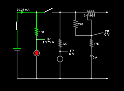
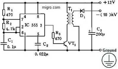
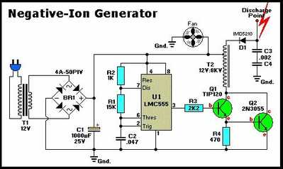
This seems pretty straight forward, but for some reason I'm having difficulty, mostly because I am very new to circuit design. I want to build a simple circuit to a device (negative ion generator) that is rated 12v DC. I just want to adjust voltage input to it from around 5v/6v to 9v from a 9v battery. I tried an adjustable voltage divider circuit with a potentiometer (see below). It varied the voltage in the range I wanted, but was getting some weird voltage leakage in the circuit. The output voltage is in the kilavolt range, so it could be I have this set up wrong. I read about using something like the LM317 for adjustable voltage regulation, is that a better option? Any suggestions?
This seems pretty straight forward, but for some reason I'm having difficulty, mostly because I am very new to circuit design. I want to build a simple circuit to a device (negative ion generator) that is rated 12v DC. I just want to adjust voltage input to it from around 5v/6v to 9v from a 9v battery. I tried an adjustable voltage divider circuit with a potentiometer (see below). It varied the voltage in the range I wanted, but was getting some weird voltage leakage in the circuit. The output voltage is in the kilavolt range, so it could be I have this set up wrong. I read about using something like the LM317 for adjustable voltage regulation, is that a better option? Any suggestions?
Not sure if you are only interested in designing and building your own circuit, or will accept an off the shelf solution like the LM317. I use the LM2596 as it can handle 3A, two times the 317. Comes in outputs of 3.3, 5, 12 and variable which is what I use. I often use 12 in, 7ish out to an LDO 5V linear regulator.
First computer 1959. Retired from my own computer company 2004.
Hardware - Expert in 1401, and 360, fairly knowledge in PC plus numerous MPU's and MCU's
Major Languages - Machine language, 360 Macro Assembler, Intel Assembler, PL/I and PL1, Pascal, Basic, C plus numerous job control and scripting languages.
Sure you can learn to be a programmer, it will take the same amount of time for me to learn to be a Doctor.
Have you looked at ion generator circuits given online?
Can you explain your thinking behind the circuit you have posted?
What do the circles, one with a red disc inside, represent?
@zander I think with this application, an off the shelf module with an IC like that might just do the trick. I was looking for something with a potentiometer instead of a trim pot to be able to adjust the voltage by hand.
@robotbuilder I have looked at ion generator circuits and the problem is that I don't know what's inside this particular generator that I own since it's in a casing and I don't want to open it. It kind of looks like this, but mine is older. My application is creating a static buildup on the body for illusionist purposes like this. It's not a common application so there's not any circuit examples for what I am doing, I want to be able to adjust the voltage for different illusions that require a slightly different amount of static buildup. The circles are status LEDs, which I eliminated the first one because the resistor was getting too hot.
@makersmarquee Ok, then the LM2596 will not be to your liking, it's a very tiny pot. I am sure you know, but just in case remember negative ions are good, positive bad.
First computer 1959. Retired from my own computer company 2004.
Hardware - Expert in 1401, and 360, fairly knowledge in PC plus numerous MPU's and MCU's
Major Languages - Machine language, 360 Macro Assembler, Intel Assembler, PL/I and PL1, Pascal, Basic, C plus numerous job control and scripting languages.
Sure you can learn to be a programmer, it will take the same amount of time for me to learn to be a Doctor.
@makersmarquee What you could do is take something like an LM2596, and de-solder the existing trim pot and replace it with a more realistic pot. Mount the LM2596 and new pot on a small board and if the POT range is a problem, add a fixed resistor to limit the range. Also, I think you want a linear pot not a tapered or other kind of pot.
First computer 1959. Retired from my own computer company 2004.
Hardware - Expert in 1401, and 360, fairly knowledge in PC plus numerous MPU's and MCU's
Major Languages - Machine language, 360 Macro Assembler, Intel Assembler, PL/I and PL1, Pascal, Basic, C plus numerous job control and scripting languages.
Sure you can learn to be a programmer, it will take the same amount of time for me to learn to be a Doctor.
@robotbuilder That is the link the OP posted. Second link on the post at https://forum.dronebotworkshop.com/postid/37604/
First computer 1959. Retired from my own computer company 2004.
Hardware - Expert in 1401, and 360, fairly knowledge in PC plus numerous MPU's and MCU's
Major Languages - Machine language, 360 Macro Assembler, Intel Assembler, PL/I and PL1, Pascal, Basic, C plus numerous job control and scripting languages.
Sure you can learn to be a programmer, it will take the same amount of time for me to learn to be a Doctor.
@robotbuilder I wish those links were a different colour, maybe underlined etc so they stood out more.
First computer 1959. Retired from my own computer company 2004.
Hardware - Expert in 1401, and 360, fairly knowledge in PC plus numerous MPU's and MCU's
Major Languages - Machine language, 360 Macro Assembler, Intel Assembler, PL/I and PL1, Pascal, Basic, C plus numerous job control and scripting languages.
Sure you can learn to be a programmer, it will take the same amount of time for me to learn to be a Doctor.
@robotbuilder That is the link the OP posted. Second link on the post at https://forum.dronebotworkshop.com/postid/37604/
Doesn't he want to make a negative ion generator circuit? This link doesn't explain that, it just uses one. I can't figure out the circuit given. Don't you need a circuit that is an oscillator where the voltage in increased using a transformer and a high voltage capacitor? Or one of those voltage multiplier circuits using diodes and capacitors?
@robotbuilder @makersmarquee TBH, I am confused. I thought he was wanting a device for his illusionist act. Apparently, according to him, different amounts of static electricity produce different illusions. He then goes on to say the negative ion generator he has somehow fits into the solution. I know that those generators produce a high voltage, but I don't know if it's high enough or too high. Of course, you are right, there are plenty of circuit designs that can produce high voltage with low current. Obviously, great care must be exercised so that heart failure is NOT a possibility.
I think we can agree he needs to give us more information.
First computer 1959. Retired from my own computer company 2004.
Hardware - Expert in 1401, and 360, fairly knowledge in PC plus numerous MPU's and MCU's
Major Languages - Machine language, 360 Macro Assembler, Intel Assembler, PL/I and PL1, Pascal, Basic, C plus numerous job control and scripting languages.
Sure you can learn to be a programmer, it will take the same amount of time for me to learn to be a Doctor.
Have you looked at ion generator circuits given online?
Can you explain your thinking behind the circuit you have posted?
What do the circles, one with a red disc inside, represent?
@robotbuilder, @makersmarquee FYI...the circles in the schematic with the red dots are circuit symbols for LED in simulation software like TinkerCad, and falstad circuit simulator. The OP said that he wanted to regulate 5-6V to 9V, so I assume that that battery voltage is 9 volts in his schematic, although it's not shown..The voltage at TP of ~1.975v, is the typical voltage drop of a red LED..but his circuit shows 70.25mA through the 100 ohm and LED, which would destroy the LED for sure! If the 70.25mA is flowing through the 100 ohm, then, 7.025V dropped across the 100 ohm resistor, 9V-1.975V=7.025V.... power dissipated would be 0.49 watts! , max is 130mW.
see link: http://lednique.com/datasheet-current/
Changing the two resistor in the circuit with the LED's to 360 ohm, outs the current at ~19.5mA ..as for the rest of the circuit an LM 317 adjustable can be used, depending on wat the circuit current requirements are..eg: less than 1Amp.
regards,
LouisR
LouisR
FYI...the circles in the schematic with the red dots are circuit symbols for LED in simulation software like TinkerCad, and falstad circuit simulator.
Yes I know now. I assume a real circuit has not been made. Strange the circuit simulator doesn't label the components or show the voltage. Given the actual supply voltage and component values the expected output range is easy to calculate. Using the LM317 would be a better option and there are plenty of examples online.
If the ion generator circuit is using a transformer I would have assumed its output voltage was fixed unless you had a variable transformer? I don't see how a variable 5-6V to 9V supply controls whatever ion generator circuit we are talking about?
@robotbuilder I do have an off-the-shelf ion generator module that looks like the one linked below. It doesn't have an output listed, but it does say it's rated DC 12V input. When I connect the ion generator straight to the benchtop power supply, the static electricity generated is varied depending on the voltage input inside that range and I find that 12V is too powerful static generation for my requirements. I don't have instrumentation that is able to measure the large voltage output from this generator, so I can only tell you that the intensity of the static varies depending on the input voltage. I find other examples of the same product output around 2-10kV depending on the voltage input. I just find that using a 9V battery as done in the previous examples of this illusion that I can find online makes the most sense. At 9V supply the Ion Generator runs at 0.05 amps and 0.46 watts and if I put the output lead directly to earth ground it goes to 0.50 watts max. I measured the resistance and capacitance on the supply leads to the generator and I get a resistance of 2.58MΩ and a capacitance of 0.067nF, not sure if that tells you anything about the circuit. Is there anything else I can look at to help determine more about that circuit besides opening it up? I can do that if it would help, it's just that it's in a solid, well sealed case.
I apologize about the circuit I posted originally. I didn't explain that I created that simple voltage divider circuit in a sim and wanted to connect the right side of that circuit to the leads of the generator. Here are a few generator circuits that I found online, but again, I don't need to make one, just need to vary the voltage input to the one I have.
@zander is heart failure even possible at .05 amps? What more information should I provide?
If the 70.25mA is flowing through the 100 ohm, then, 7.025V dropped across the 100 ohm resistor, 9V-1.975V=7.025V.... power dissipated would be 0.49 watts! , max is 130mW.
@inst-tech Learned that the hard way, eliminated that LED anyways since it was redundant.


