Anyone have any ideas... @inst-tech, @davee
I started out thinking this was going to be falling off the log easy.
Background (Ignore as Desired)
Now, I'm all kinds of confused. All I wanted to do was see what kind of power requirements my MPU needs under various conditions - WiFi on/off, crunching numbers, sleeping. I selected a bare ESP8266-12E. In another thread, we've discussed the voltage converters and other support circuitry of a WeMos or NodeMCU from the 5V USB to the 3.3V needed by the ESP are power wasteful. This will be just what the MPU needs.
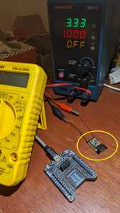
The Test Equipment
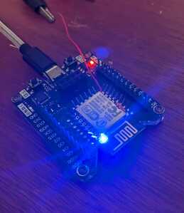
Placing in the programmer and powering by the computer's USB cable, it boots up fine and Serial Monitor shows me the Sketch is working, blinking the LED at appropriate times and I didn't screw the ESP up while soldering the wires to it. I can also measure the voltage on said wires and sure enough I get 3.3 volts being supplied through the programmer's connections. IOW, my soldering job is fine. Even with the workshop lights on, the LED blows out the camera.
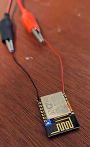
Taking it out of the programmer, I then tried to power it with the bench power supply set at 3.33V. I tried 0.3A then 1A. Turning it on, the current reading (on the PS) shows 0.000 as if it is an open circuit. I measured the voltage at the ESP's VCC/G pin pads and sure enough, it shows 3.33 volts. Turning off the workshop's lights, I can see that the LED is barely lit and constant. It is not booting up which flashes various things.
Any ideas or suggestions I can try?
Thanks!
VBR,
Inq
3 lines of code = InqPortal = Complete IoT, App, Web Server w/ GUI Admin Client, WiFi Manager, Drag & Drop File Manager, OTA, Performance Metrics, Web Socket Comms, Easy App API, All running on ESP8266...
Even usable on ESP-01S - Quickest Start Guide
@ing, Have you tried to place it back into the programmer again to see if it still boots up and runs the sketch? A no current reading in your power supply indicates an open ckt, ..but try the programmer again to varify the board is still good, and we'll go from there..
regards,
LouisR
LouisR
@ing, Have you tried to place it back into the programmer again to see if it still boots up and runs the sketch? A no current reading in your power supply indicates an open ckt, ..but try the programmer again to varify the board is still good, and we'll go from there..
regards,
LouisR
Thank you for chiming in. I did try putting it back an it works, boots up, runs, Serial output, flashes LED... IOW I haven't bricked it... yet. 🤣
Being a little fuzzy in this area, I was assuming it is my cheap bench power supply. I dug around and found a LiIon battery that was just under 3.3V and tried it and got the same results.
Then remembering all out talks about powering over wires, I did the check on the voltage drop. Even though using 30AWG, the Internet calculator said the voltage drop is down in like the 3rd decimal place.
Since I posted, I've been trying to find more detail about battery powering a bare ESP8266-12E. I'm wondering if other connections need to be made so it'll boot... like something pulled down or up. It's been a crap shoot so far. One said I need to power the EN pin, others say no, others. Most are concerned with programming it and that does need special handling. I'll just use the programmer for that. So far, I have not found anything JUST about powering it.
VBR,
Inq
3 lines of code = InqPortal = Complete IoT, App, Web Server w/ GUI Admin Client, WiFi Manager, Drag & Drop File Manager, OTA, Performance Metrics, Web Socket Comms, Easy App API, All running on ESP8266...
Even usable on ESP-01S - Quickest Start Guide
@inq The 30AWG sounds very small. How much current and how long. Just for giggles, try 20AWG.
First computer 1959. Retired from my own computer company 2004.
Hardware - Expert in 1401, and 360, fairly knowledge in PC plus numerous MPU's and MCU's
Major Languages - Machine language, 360 Macro Assembler, Intel Assembler, PL/I and PL1, Pascal, Basic, C plus numerous job control and scripting languages.
Sure you can learn to be a programmer, it will take the same amount of time for me to learn to be a Doctor.
Hi @inq,
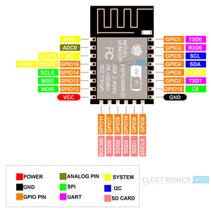
Sorry, I find myself on night owl hours before even looking at the forum, again, so too late to do the digging, but I think most ESPs require one or more pullup/pulldown resistors to enable them to figure out what configuration to wake up in. I suspect your programmer is providing such a service.
In the same vein, you might also need a capacitor as well as resistor.
Reset pin is the first favourite, but I suspect there may 3 or 4.
Do a bit of reading, or prodding, and see if you can find it .. if not post again and I'll have another look.
By the way your wires and soldering are fine .. I think it is just your ESP needs a little gentle caressing around a few of its pins with some friendly Rs and Cs to make it feel loved with the right potentials!
Good luck. Let me know how how you get on. Best wishes, Dave
@inq The 30AWG sounds very small. How much current and how long. Just for giggles, try 20AWG.
Oh... they're only about 2 inches long. The voltage drop calculator said a 300 mA, it only dropped something like 0.003V. I couldn't measure a drop at all with my volt meter... above 3.3V still.
3 lines of code = InqPortal = Complete IoT, App, Web Server w/ GUI Admin Client, WiFi Manager, Drag & Drop File Manager, OTA, Performance Metrics, Web Socket Comms, Easy App API, All running on ESP8266...
Even usable on ESP-01S - Quickest Start Guide
Hi @inq,
Sorry, I find myself on night owl hours before even looking at the forum, again, so too late to do the digging, but I think most ESPs require one or more pullup/pulldown resistors to enable them to figure out what configuration to wake up in. I suspect your programmer is providing such a service.
In the same vein, you might also need a capacitor as well as resistor.
Reset pin is the first favourite, but I suspect there may 3 or 4.
Do a bit of reading, or prodding, and see if you can find it .. if not post again and I'll have another look.
By the way your wires and soldering are fine .. I think it is just your ESP needs a little gentle caressing around a few of its pins with some friendly Rs and Cs to make it feel loved with the right potentials!
Good luck. Let me know how how you get on. Best wishes, Dave
Owl hour - Me also. 2:40AM here!
I finally found an article that isn't wiring for programming. It also has powering suggestion. I've order the pieces...here Thursday.
- (2) 1000 ohm resistors
- (1) 1000 uF capacitor
- (1) HT7333-A voltage regulator. Says only 4uA quiescent current. SCORE!
Question you might answer. I'm sure they had good reason, but from the cheap seats, I can' see it... why would a hardware designer, design an MPU module that does all the things an ESP will do, yet it can't run without these two lousy pull-up/pull-down resistors? I can see having to add components for programming... but run-time?! I can see the capacitor not being part of it since, it's not needed with other power supply options.
VBR,
Inq
3 lines of code = InqPortal = Complete IoT, App, Web Server w/ GUI Admin Client, WiFi Manager, Drag & Drop File Manager, OTA, Performance Metrics, Web Socket Comms, Easy App API, All running on ESP8266...
Even usable on ESP-01S - Quickest Start Guide
@inq I am real curious to hear the results.
First computer 1959. Retired from my own computer company 2004.
Hardware - Expert in 1401, and 360, fairly knowledge in PC plus numerous MPU's and MCU's
Major Languages - Machine language, 360 Macro Assembler, Intel Assembler, PL/I and PL1, Pascal, Basic, C plus numerous job control and scripting languages.
Sure you can learn to be a programmer, it will take the same amount of time for me to learn to be a Doctor.
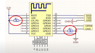
That was it! I used this circuit from the "Guy with Swiss Accent".
The one resistor 1Kohm was what it needed and it booted right up and worked as programmed.
3 lines of code = InqPortal = Complete IoT, App, Web Server w/ GUI Admin Client, WiFi Manager, Drag & Drop File Manager, OTA, Performance Metrics, Web Socket Comms, Easy App API, All running on ESP8266...
Even usable on ESP-01S - Quickest Start Guide
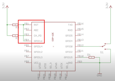
@inq Everything in green is what you added? Perhaps for the benefit of everyone you could briefly describe all the mods?
Here is what I see, please correct any mistakes and flesh out what is missing. GREAT work, now off to add a few ESP
1. GPIO0 to switch with G and 3.3V
2. GPIO15 to R?? to G
3.GND to GND?
4. GPIO16 to RST
5. CH_PD to R? to 3.3VDC
6. RST to R? to 3.3VDC
First computer 1959. Retired from my own computer company 2004.
Hardware - Expert in 1401, and 360, fairly knowledge in PC plus numerous MPU's and MCU's
Major Languages - Machine language, 360 Macro Assembler, Intel Assembler, PL/I and PL1, Pascal, Basic, C plus numerous job control and scripting languages.
Sure you can learn to be a programmer, it will take the same amount of time for me to learn to be a Doctor.
@inq Everything in green is what you added? Perhaps for the benefit of everyone you could briefly describe all the mods?
Here is what I see, please correct any mistakes and flesh out what is missing. GREAT work, now off to add a few ESP
1. GPIO0 to switch with G and 3.3V
2. GPIO15 to R?? to G
3.GND to GND?
4. GPIO16 to RST
5. CH_PD to R? to 3.3VDC
6. RST to R? to 3.3VDC
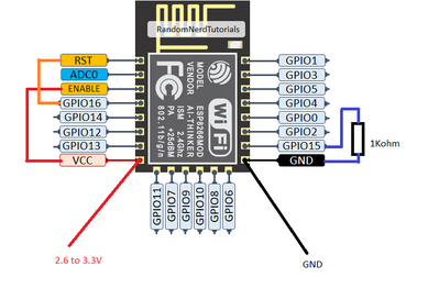
This is what I have now. I did have the VCC to Enable, and GPIO16 to RST when I started this thread. From the previous drawing from Swiss Guy, I first added this 1K from GND to GPIO15 and tried it. It worked. I didn't add the other resistor.
3 lines of code = InqPortal = Complete IoT, App, Web Server w/ GUI Admin Client, WiFi Manager, Drag & Drop File Manager, OTA, Performance Metrics, Web Socket Comms, Easy App API, All running on ESP8266...
Even usable on ESP-01S - Quickest Start Guide
@inq I think there is more than 1 resistor missing, I looked again at the Swiss Guy and see 2 resistors and the 3.3 via one of those resistors to RST. Not sure what that will affect. The good news is by leaving out the pull up on EN. That enables Hibernate mode unless your ESP01 chip ends with an S as in ESP01S or ESP12S because they have 12K pullups inside the can.
Have a look
First computer 1959. Retired from my own computer company 2004.
Hardware - Expert in 1401, and 360, fairly knowledge in PC plus numerous MPU's and MCU's
Major Languages - Machine language, 360 Macro Assembler, Intel Assembler, PL/I and PL1, Pascal, Basic, C plus numerous job control and scripting languages.
Sure you can learn to be a programmer, it will take the same amount of time for me to learn to be a Doctor.
@inq AHA, the Enable pin is sometimes labelled as CH_PD. That stands for Chip Power Down!!! That pin must be pulled high for the chip to operate and if low causes the Power Down or Hibernate mode (3uA). HOWEVER for chips ending in S the pullup 12K is either inside the can and not easily removed, or on the board and easily removed.
Sorry, I am tired as hell and dealing with 3 other issues so I might have this wrong, but check the video I posted and double check that against the Swiss Guy. I don;t think he knows about the Hibernate trick.
First computer 1959. Retired from my own computer company 2004.
Hardware - Expert in 1401, and 360, fairly knowledge in PC plus numerous MPU's and MCU's
Major Languages - Machine language, 360 Macro Assembler, Intel Assembler, PL/I and PL1, Pascal, Basic, C plus numerous job control and scripting languages.
Sure you can learn to be a programmer, it will take the same amount of time for me to learn to be a Doctor.
@inq I think there is more than 1 resistor missing, I looked again at the Swiss Guy and see 2 resistors and the 3.3 via one of those resistors to RST. Not sure what that will affect. The good news is by leaving out the pull up on EN. That enables Hibernate mode unless your ESP01 chip ends with an S as in ESP01S or ESP12S because they have 12K pullups inside the can.
Have a look
Watched it... but it sounds like you must have some kind of components to turn it back on. I'll need to get the LoRa stuff in to see how much power and how long it needs to run.
At the moment, I'm guessing three seconds to boot, gather the sensor data, send it and wait for confirmation. The LoRa doesn't have to be on for the first two parts, but to be conservative. So:
Running
- 120 mA LoRa
- 15 mA ESP8266
- ?? other stuff, sensors, voltage regulator
- Call it ~150mA for 3 seconds
Sleep
- 19 uA ESP8266
- 4 uA voltage regulator
If I do 4 samples per hour => 2000 mAh LiIon 18650, I should get a battery life approaching 159 days. That is way more than I need. But, got to wait for reality to set in. 🤣
3 lines of code = InqPortal = Complete IoT, App, Web Server w/ GUI Admin Client, WiFi Manager, Drag & Drop File Manager, OTA, Performance Metrics, Web Socket Comms, Easy App API, All running on ESP8266...
Even usable on ESP-01S - Quickest Start Guide
@inq No other components, it's just another level of sleep BUT I will test it when I get some ESP01 boards. This is interesting, but I think I will still use the power off and on using the DS3231 RTC module for my cameras. Given your use case, if you are not using WiFi then even light sleep may last long enough but deep sleep will for sure.
First computer 1959. Retired from my own computer company 2004.
Hardware - Expert in 1401, and 360, fairly knowledge in PC plus numerous MPU's and MCU's
Major Languages - Machine language, 360 Macro Assembler, Intel Assembler, PL/I and PL1, Pascal, Basic, C plus numerous job control and scripting languages.
Sure you can learn to be a programmer, it will take the same amount of time for me to learn to be a Doctor.

