Hello I started designing a CNC machine but I am confused over all linear rails and ball screw vendors that's out there (Amazon, Ali, Banggood, Temu.....) (Linear rails 20mm x 1000mm , 750mm and 450mm times two, ball screw 1000mm, 750mm and 450mm) ware to find good quality and to a decent price.
The same for electronic equipment!
4x Nema 23 3v?
Stepper drivers?
Arduino or?
Power supply?
End stops?
How to connect?
Anything else?
Need to understand what to buy and from whom.
This topic was modified 6 months ago 2 times by TM-comp
TM-comp Sorry for my bad English not my native tongue!
I have built several CNC systems over the years. I use Mach3 software to deliver the commands to the motors so I can send G-code commands to determine the direction and speed of motion on multiple axes. Mach4 is the current version available, and there are other options including open source CNC programs. You could perhaps use Arduino to control something simple, in fact I made an electric door using Arduino boards and stepper motor shields. If you are masochistic you might even attempt a full blown CNC, but for the cost of software like Mach4, I question the wisdom of this. I have been running a 3 axis milling machine using Mach3 for about 15 years, and have machined many 3 dimensional parts, odd shapes, etc. I also use FreeCAD to create 3 dimensional parts saved as step files, then use BobCADCAM to create the G-code to tell Mach3 how to machine them. That is a whole other subject.
I have used cheap linear rails from ebay, and found them to be of good quality. One version that might work for you is the SBR series
. They are available in different diameters and lengths on ebay, amazon, etc.
As for ball screws, it depends on what you need in terms of accuracy and quality. Most cheap ball screws are metric, and turned rather than precision ground. This is not necessarily bad, but may result in a small amount of error in motion. I have found the backlash of the cheap ball screws to be virtually zero, and motion to be smooth. If you want accuracy of better than about 0.001 inch per foot of length, then consider precision ground ball screws, but at a much higher cost. In general larger diameter linear rails and ball screws will be stiffer and less prone to deflection under load. If you do not need super accuracy (maybe a plasma cutter for example), then you could consider some of the systems designed around extruded aluminum for rails (8020 is one such product). Acme lead screws are good for some applications, but tend to have backlash that may cause problems. Standard threaded rod is a cheaper but less accurate and less durable alternative.
I have used stepper motors, servo motors, and the newer stepper motors with encoders.
In general a stepper motor will be the cheapest solution, but they have limitations on RPM, and if overloaded can lose steps, leading to errors that can be hard to find. A stepper motor and driver combination is designed to use a very simple electrical signal (step & direction), usually two 5 volt square (or rectangular) waves, one to determine direction, the other to tell the motor to step. The motor will move one step for each pulse on the step pin. In fact, all three types of motor can have a driver module that may accept step and direction signals. Usually stepper motors are limited to about 1000 RPM maximum, but operating at a higher voltage than rated will result in faster operation. A stepper motor is normally rated for perhaps 3 volts, which means if you use a 3 volt power supply, the motor will not exceed its rated current. Usually the stepper driver electronics is designed to operate at a higher voltage (perhaps 24-32 volts) and to have a current limiting function that can be adjusted to avoid overheating the motor due to excessive current. This will result in faster operation and less chance of missed steps. Stepper motors that move in steps create a jerky motion that can cause vibrations, but that may or may not be a problem depending on your system requirements. Be sure to check the maximum torque values for any stepper motor before purchasing.
Stepper motors with encoder feedback are a great alternative since the controller will continue sending steps to the motor until it reaches the desired position, correcting for the occasional missed step. Most of these controllers allow micro-stepping. For a stepper motor operated in full step mode, usually 200 steps will produce a full 360 degrees of revolution. In full step mode the current delivered to the motor is at the full rated value for two windings. One step will reverse the current on one winding at a time, resulting in a rotation of 1.8 degrees (1/200 of a revolution). It is also possible to only deliver a current waveform that changes by a fraction for each "Step pulse", which will rotate the motor a fraction of the 1.8 degrees. This is called micro-stepping, and can produce a small fraction of 1.8 degrees of rotation. In fact if a triangular current pulse is used to drive both windings on the motor, perfectly smooth rotation can be achieved with 1.8 degrees of rotation reached at the peak of each current pulse. The downside of micro-stepping is reduced torque since full torque is achieved only for maximum rated current, and some tuning may be required to achieve best performance.
Servo motors are another option, often more costly. They are available in both brush type and brush-less. They require motor amplifiers or drivers designed to apply a voltage to the motor forcing it to turn in a particular direction until the attached encoder senses it has arrived at the desired location. The driver must be designed to match the motor type, and to handle the required voltage and current of the motor. Heat sinks may be required for the amplifiers. Servo motors also move in steps, but the amplifiers have built in acceleration and deceleration, current limiting, and other tuning parameters to allow smooth motion. Due to the higher RPM these motors may use timing belts and pulleys connecting them to the ball screws to achieve the desired maximum speed while multiplying the torque.
These servo motors often operate at higher voltages, perhaps 80-140 volts or more. They have an RPM rating that is usually higher than stepper motors. They will have a RPM per volt rating (e.g. 50 RPM/volt). If this motor is operated from a 10 volt power supply, it will have a maximum RPM of 10*50=500 RPM. Operation at 100 volts will increase the maximum RPM to 5000. The actual speed will often be less than maximum as determined by the driver electronics and the rate of step signals.
I have used cheap power supplies with good success, and even built my own linear 75 volt 20 Amp supply from an old microwave transformer (again another topic).
How to connect is a broad topic that is beyond the scope of this discussion, but I would be happy to try to answer question specific to some product you are considering.
The downside of micro-stepping is reduced torque since full torque is achieved only for maximum rated current, and some tuning may be required to achieve best performance
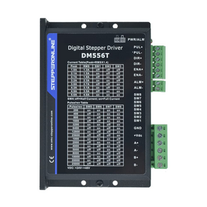
Is this something with the larger (non 3D printer) drivers for the bigger Nema-23 steppers? The reason I ask...
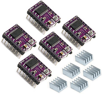
versus
Full steps mean only one set of coils are active. Whereas, any intermediate step in micros stepping both sets of coils are active and the tiny 3D printer drivers are usually rated for maximum current per coil, not per driver. IOW, at the half step both coils can be delivering 100% and thus be exerting 141% of the force of a single coil at a full step. @davee did a long dissertation on this and I've seen it in practice. Although I did believe what @davee said (charts and tables from manufacturers are hard to argue with), I did want to see it in action. I could set my robot to use either full steps or 1/32 micro-stepping. Having it go to a given speed, it would need to accelerate (torque being applied). As I asked it to higher speeds in less time requiring more torque, the micro-stepping mode would clearly reach higher accelerations. The full-step mode would at lower rates finally start chattering and not move the bot at all. Anyway, wondered if the big box drivers work differently???
Another question - You obviously have a lot of experience doing these linear movement/track type projects and know when you can economize on certain pieces and when you can't. I have this project that has been back-burnered for years. One of the track dimensions would be 50'. I don't need all that much accuracy (+/- 0.1" would be fine) or extreme forces (< 100 lbs). Have you ever tried using the 10' length hanging ceiling threaded rod? Using bronze nuts as the mating follower it seems to run fairly smoothly and there isn't any play that I can feel.
3 lines of code = InqPortal = Complete IoT, App, Web Server w/ GUI Admin Client, WiFi Manager, Drag & Drop File Manager, OTA, Performance Metrics, Web Socket Comms, Easy App API, All running on ESP8266... Even usable on ESP-01S - Quickest Start Guide
Please note, these comments are purely my interpretation of what I have read, and are not based on any personal research, knowledge or experience. Whilst I apologise for any additional errors I have introduced, I am neither supporting or denying any of the suggestions obtained from the forums.
The highest total current in the microstepping occurs when both coils are at 70.7%, which results in the total that you stated of 141(.4) %. The drive current to an individual coil is only 100% at the the full step positions, when the current to the other coil is zero.
I haven't checked, but I would imagine the low cost 'boxed' driver controller units will aim for the same microstepping rules as the small PCB based modules, although there are a number of different integrated circuits available to construct the small PC modules, some of which offer more sophisticated algorithms, to allow for inertia, etc. than others. Presumably, there will also be performance variations in the different boxed units as well.
The torque versus stepping options position appears to be quite complex, because there are a number of effects interacting.
When the motor is stationary, then the motor is not generating any back emf (voltage), the current can only be reduced by inductance immediately following the last step or micro-step and hence after a few moments, the current will reach the specified value, and there are no mechanical resonances, etc. arising from the motion, so that it is purely a 'holding torque' scenario.
However, when the motor is being microstepped or stepped, with the motor moving, the consequences of different effects interact to produce a more complex picture. Part of the picture appears to include the suggestion that some more sophisticated controller/drivers may perform more consistently over a wide range of speeds because they include more comprehensive compensation mechanisms, but at the 'simpler' end, I note the following suggestions:
At stationary and low speeds, the driver is able to control the current, so that the motor is being current controlled, because the voltage supply to the driver is high enough for the current regulator to overcome the motor back emf, and (presumably much of) the inductive current limiting. However, beyond a certain speed, the supply voltage becomes the limiting factor, as the regulator is at '100%' of its range, causing the motor to be voltage driven. Obviously, the higher applied voltage, the larger the range of available adjustment of current control.
At low speeds, the microstepping provides not only a much smoother motion, but also a higher effective dynamic torque than full stepping. Beyond a certain speed, which the forum discussion suggests is about 3-4 rpm, full stepping becomes more effective as it maintains a slightly higher torque waveform.
At higher speed, a further problem of mid-band resonance occurs. It is claimed the the more sophisticated controller/drivers can mitigate this effect. Of course, not all applications may require the motor to operate this quickly.
The more sophisticated driver/controllers may make use of additional sensors fitted to (or close to) the motor to detect certain unwanted behaviour, so that the controller can modify the drive performance to avoid the conditions that provoke the problem.
I hope this additional discussion is of some benefit. Obviously, it is little more than speculation on my part, so please check out any options independently before committing to expenditure of money and effort.
We use cookies on the DroneBot Workshop Forums to give you the most relevant experience by remembering your preferences and repeat visits. By clicking “Accept”, you consent to the use of ALL the cookies.
This website uses cookies to improve your experience while you navigate through the website. Out of these, the cookies that are categorized as necessary are stored on your browser as they are essential for the working of basic functionalities of the website. We also use third-party cookies that help us analyze and understand how you use this website. These cookies will be stored in your browser only with your consent. You also have the option to opt-out of these cookies. But opting out of some of these cookies may affect your browsing experience.
Necessary cookies are absolutely essential for the website to function properly. This category only includes cookies that ensures basic functionalities and security features of the website. These cookies do not store any personal information.
Any cookies that may not be particularly necessary for the website to function and is used specifically to collect user personal data via analytics, ads, other embedded contents are termed as non-necessary cookies. It is mandatory to procure user consent prior to running these cookies on your website.