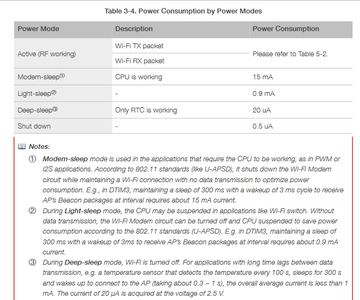
@inq No other components, it's just another level of sleep BUT I will test it when I get some ESP01 boards. This is interesting, but I think I will still use the power off and on using the DS3231 RTC module for my cameras. Given your use case, if you are not using WiFi then even light sleep may last long enough but deep sleep will for sure.
According to the video... something has to put the resistor back in place... IOW an external switch. Maybe, I misunderstood what was said, but that's how I interpreted it. If you can get it to work... let me know.
But... even if it does get the MPU to 3uA, that only increases the battery life from 159 days to 164 days.
3 lines of code = InqPortal = Complete IoT, App, Web Server w/ GUI Admin Client, WiFi Manager, Drag & Drop File Manager, OTA, Performance Metrics, Web Socket Comms, Easy App API, All running on ESP8266...
Even usable on ESP-01S - Quickest Start Guide
@inq Sounds reasonable, but until I can test I don't know. I really don't understand the math of going from 19uA to 3uA and the days only change from 159 to 164. Seems like it should be a lot more. The esp01 board collection doesn't arrive until between Nov 29 and Dec 19. There are 9 different boards in the set. I just looked at an esp32 posting re deepSleep and hibernation and in both cases it looks like they were using a pin to wakr them up. I will reserve judgement until I can do my own test.
First computer 1959. Retired from my own computer company 2004.
Hardware - Expert in 1401, and 360, fairly knowledge in PC plus numerous MPU's and MCU's
Major Languages - Machine language, 360 Macro Assembler, Intel Assembler, PL/I and PL1, Pascal, Basic, C plus numerous job control and scripting languages.
My personal scorecard is now 1 PC hardware fix (circa 1982), 1 open source fix (at age 82), and 2 zero day bugs in a major OS.
Hi @inq,
Good to see you tracked down some useful suggestions and got it working.
I have down a little digging and I suspect the 'bare' ESP8266 module you have is the ESP8266-12x type, where x is presently 'E' or 'F'. I am not sure, but I think I recall the only significant difference between E & F is the antenna pattern on the PCB.
There is short datasheet at
https://docs.ai-thinker.com/_media/esp8266/docs/esp-12f_product_specification_en.pdf
========================
The ESP range take a quick peek at several pins during the first part of the boot process, to determine what mode is to be booted ... after that point in time, the pins can be used for 'normal' GPIO functions, but obviously if they are connected to something like a sensor, some care is needed to ensure they are held at the required level at boot time.
======
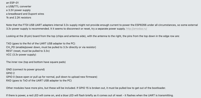
Since both low and high levels are valid in different circumstances for these pins, it is necessary to addthe extra resistors, etc. externally. That said, it is necessary to read multiple documents to track down what is required, which makes it more tricky than it needs to be. For future reference, i have caught a few snippets below.
------------
The reference for the ESP-12F includes the table:
So clearly, to persuade it to boot from the programme in Flash, it will need GPIO15 = 0, GPIO 0=1, GPIO2 = 1
The ESP8266 processor chip hidden alongside other parts under the metal can has a datasheet at
https://www.espressif.com/sites/default/files/documentation/0a-esp8266ex_datasheet_en.pdf
Snips from this include:
Note:
1. GPIO2, GPIO0, and MTDO are used to select booting mode and the SDIO mode;
2. U0TXD should not be pulled externally to a low logic level during the powering-up
===============================================
NB This datasheet includes:
but the ESP8266-12F datasheet says the module temperature range is
Probably not a problem for this project, but you might find it useful to know in another project.
===============================================
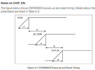
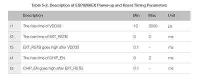
This diagram and table shows the timing expected between 3.3V power up, nRESET pin and Chip Enable pin.
NOTE: Whilst the final state all high will be achieved the circuit suggestions, I suspect some will contradict these timing requirements. Obviously, if you have a working system, no problem, but if you get problems with booting, this might need to be revisited. It is not difficult ... probably a resistor and capacitor.
=================
Probably much more than you need for now, but these little details can be part of a future problem, and hopefully an answer!!
Best wishes, Dave
PS, sorry I haven't watched Swiss Accent Guy's video, but noting the comment "According to the video... something has to put the resistor back in place..", if it refers to the pull up on reset pin in his drawing, I suspect it is in error ... the circuit in the reference for ESP8266-12F I quote above shows a resistor & capacitor pull up ... adding a resistor should be unnecessary, and might even break the timing requirement between power on and reset. Of course, there maybe other similar looking modules/revisions that require a pull up.
There is short datasheet at
https://docs.ai-thinker.com/_media/esp8266/docs/esp-12f_product_specification_en.pdf
I have a wide selection of their boards and they make about 20 different versions. Basically from what I can see, like you mention, they vary by how many of the tiny universal chip's pins are exposed for customer use and type of antenna being: PCB, some kind of ceramic antenna or a connector for external.
The ESP range take a quick peek at several pins during the first part of the boot process, to determine what mode is to be booted ... after that point in time, the pins can be used for 'normal' GPIO functions, but obviously if they are connected to something like a sensor, some care is needed to ensure they are held at the required level at boot time.
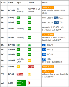
I do have to admit the Arduino (brand) of boards are far better about this than ESP. From what I remember. I haven't used a true Arduino board in ten years... they didn't do this role sharing of a pin. I bet when you do a project, you start with the hardware design 🤣 and pre-figure this out. Me... I write the program first, debug and get it fully working on the bare board... then start adding any external hardware - one piece at a time. Say... adding one sensor, replace the software snippet with the actual sensor feed, then add the next hardware piece. Invariably, I run into the problems as you describe. I'm holding a pin the wrong way and it won't take the upload or it won't boot. I simply rearrange which pins I use for what functionality. This chart from Random Nerds has always kept me between the fence posts.
The main take-away from your post that I see in relation to what I have wired now is that the second resistor (that I didn't add from the Swiss guy's schematic) pulls up the pin so that it can boot, but software could use this pin once the Sketch is running. Whereas I have it directly wired to the VCC so it accomplishes the same thing (needing to be high for boot) but my version won't be usable by software once running. If I need that pin for something, I can just add the resistor.
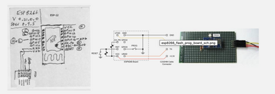
PS, sorry I haven't watched Swiss Accent Guy's video, but noting the comment "According to the video... something has to put the resistor back in place..",
Nah! That was Ron and I trading off about his video. Swiss guy didn't talk about hibernation mode. The sleep modes awake due to software setting a time. Ron's video showed (about a dozen times) of the guy physically pulling/putting the resistor in the breadboard. I took this to mean some kind of external timer hardware would need to be added to "switch" the resistor on/off.
3 lines of code = InqPortal = Complete IoT, App, Web Server w/ GUI Admin Client, WiFi Manager, Drag & Drop File Manager, OTA, Performance Metrics, Web Socket Comms, Easy App API, All running on ESP8266...
Even usable on ESP-01S - Quickest Start Guide
I think my main question for you that the Internet/Espressif docs don't touch on...
From a hardware design standpoint, why would Espressif design these PCB with the main chip and support hardware to expose the pins, yet require two extra pull-up/down resistor to be added to simply boot it? Why not build those into the PCB... so the default functionality is to boot to running mode? It would only need extra parts if it was being programmed.
I'm guessing I'm asking - is there some kind of hardcore, hardware reason or convention to not add these two resistor?
VBR,
Inq
3 lines of code = InqPortal = Complete IoT, App, Web Server w/ GUI Admin Client, WiFi Manager, Drag & Drop File Manager, OTA, Performance Metrics, Web Socket Comms, Easy App API, All running on ESP8266...
Even usable on ESP-01S - Quickest Start Guide
@inq @davee I went back and looked at the video again and indeed Dennis is right. A button is needed to come out of Hibernation mode. When I get some ESP01's I will still test to be sure but for now Hibernation mode on the 8266 is not usable in a timer scenario (and undocumented). However, on the ESP32 it is documented. I have found reputable code that seems like HIBERNATION mode with timer wake up is possible. I will report back when I have completed my experiments.
First computer 1959. Retired from my own computer company 2004.
Hardware - Expert in 1401, and 360, fairly knowledge in PC plus numerous MPU's and MCU's
Major Languages - Machine language, 360 Macro Assembler, Intel Assembler, PL/I and PL1, Pascal, Basic, C plus numerous job control and scripting languages.
My personal scorecard is now 1 PC hardware fix (circa 1982), 1 open source fix (at age 82), and 2 zero day bugs in a major OS.
@inq Some resistors may be 'missing' because a raw chip is NOT a development board.
That is not the situation that I'm asking about.
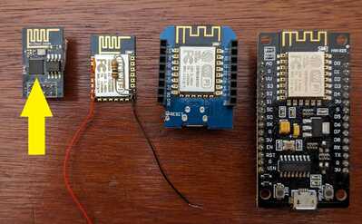
In the image below, from left to right is: ESP-01S, Bare ESP-12E, WeMos, NodeMCU. These are all development boards. The ACTUAL ESP8266 chip is being pointed to by the yellow arrow. We (the Arduino community, hobbyist) don't use just the chip. The simplest (ESP-01) has it, a separate memory chip and a bunch of support stuff (including resistors) to make it work on the tiny PCB. The ESP-12E has the same stuff under the metal box and simply exposes more of the chip's pins on its PCB. The WeMos and NodeMCU are 3rd party vendors that simply add USB communications, 5V to 3.3V voltage regulators and upsize the pin spacing to fit breadboards. If you'll note they simply have the ESP-12E daughter PCB soldered to their larger PCB.
The question I'm putting to @davee or anyone that can answer it... is why would someone at the ESP-01, ESP-12E design level not add those 2 more resistors and make the default behavior of the board able to run. Both the ESP-01 and bare ESP-12E require extra components to run or program.
My logic suggests to make one of those modes the default and simply add components for the other mode - I'd choose running as the default. I'm wondering why a real EE person didn't choose either? I'm sure they had a reason, I just can't think of a reason why.
VBR,
Inq
3 lines of code = InqPortal = Complete IoT, App, Web Server w/ GUI Admin Client, WiFi Manager, Drag & Drop File Manager, OTA, Performance Metrics, Web Socket Comms, Easy App API, All running on ESP8266...
Even usable on ESP-01S - Quickest Start Guide
@inq I think that's a reasonable question and I know of no good reason not to. I did some googling and found a few things of interest. What I find of GREAT interest is the snippet that says pulled HIGH or left FLOATING. My understanding has been that floating is BAD, either pull it HI or LO. I don't recall where I found all those but at least one had Espressif in the URL. So the net is GPIO15 must be pulled low, RST and CH_PD must be pulled high. On a Dev board GPIO00 is the BOOT pin and the RST pin will have a switch across the resistor.
First computer 1959. Retired from my own computer company 2004.
Hardware - Expert in 1401, and 360, fairly knowledge in PC plus numerous MPU's and MCU's
Major Languages - Machine language, 360 Macro Assembler, Intel Assembler, PL/I and PL1, Pascal, Basic, C plus numerous job control and scripting languages.
My personal scorecard is now 1 PC hardware fix (circa 1982), 1 open source fix (at age 82), and 2 zero day bugs in a major OS.
What I find of GREAT interest is the snippet that says pulled HIGH or left FLOATING. My understanding has been that floating is BAD, either pull it HI or LO.
EXACTLY - Like you pointed out earlier and how SOME ESP's have built-in pull-up / down resistors and some don't. Your video even shows de-soldering them so they can get that hibernation mode available. It all feels very wishy-washy and I expect there is some deeper hardware chip or board engineering reason that us at the user level are missing.
It definitely makes my butt itch? 🤣
VBR,
Inq
PS - Kind of hoping the electronic experts @davee, @inst-tech will chime in and tell us why or to at least get over it... that it's made in China. Kind of like a form of Reverse Polish Notation... different set of logic behind it. 😋
3 lines of code = InqPortal = Complete IoT, App, Web Server w/ GUI Admin Client, WiFi Manager, Drag & Drop File Manager, OTA, Performance Metrics, Web Socket Comms, Easy App API, All running on ESP8266...
Even usable on ESP-01S - Quickest Start Guide
@inq I suspect it just comes down to $$$
First computer 1959. Retired from my own computer company 2004.
Hardware - Expert in 1401, and 360, fairly knowledge in PC plus numerous MPU's and MCU's
Major Languages - Machine language, 360 Macro Assembler, Intel Assembler, PL/I and PL1, Pascal, Basic, C plus numerous job control and scripting languages.
My personal scorecard is now 1 PC hardware fix (circa 1982), 1 open source fix (at age 82), and 2 zero day bugs in a major OS.
Hi @inq,
I am not sure that there is a 'hard' reason for the choices of which resistor to add I envisage it as more of a case of fitting what they thought was necessary. I agree with Ron's (@zander) comment about this not being a development board, and add a few words on the subject further down .
-------------
Sorry Inq, I don't know if you are familiar with the principle of using a resistor and capacitor as a time delay. It is a fundamental part of electical circuits, but often gets ignored, as if everyone is born with the knowledge. So if you are familiar, sorry for my doubting; please skip the next couple of lines. If not, maybe a little background reading would be helpful ... something like:
https://www.electronics-tutorials.ws/rc/rc_1.html
If anything is confusing, please ask.
--------------
According to the ESP826-12F circuit diagram, the module includes a resistor and capacitor time delay to the reset pin, which is powered from the power pin. Hopefully they have chosen the resistor-capacitor combination to provide the right delay between the two rising edges. (ie Reset should be held low long enough for the power to stabilise at power on. My excerpts in my last message showed the sequence and timing requirements.)
I have been been reasonably impressed by Swiss Accent Guy's videos in the past, but I am more dubious about the wisdom previously attributed to him in the message above, albeit he has almost certainly built it, and I have only looked at the data sheet, so I could well be in error. In addition, some modules 'in the wild', may not match the datasheet.
---------
Adding resistor feed or direct connections to the reset pin from the power input risks breaking the timing relationship provided by the internal resistor-capacitor, which is why I have my doubts about that external resistor, or worse a direct connection to the power line:
In the event of a unit design having a power supply which takes a long time to stabilise, I can imagine fitting an extra capacitor, extending the time delay, causing the boot to be delayed, but adding a resistor as shown can only shorten the time. This may be acceptable if the designer knows the power supply characteristics, but in most cases, extending the time to boot by a few milliseconds is a trivial annoyance compared to increasing the risk that it fails to boot correctly.
On a similar vein of thought, the chip power down pin should be held low until after the reset pin has been allowed to rise.
Connecting the reset and chip pins together means they will rise simultaneously, which is apparently pushing one's luck, as the datasheet shows a minimum delay requirement of 0.1 milliseconds,
Whilst providing a separate resistor feed from power, with no capacitor, as Swiss Accent Guy apparently does, implies the chip power down pin is likely to rise before the reset pin, which is definitely contrary to the data sheet.
I expected to see a resistor-capacitor, powered from the reset pin to ensure it the chip power down could not go high prior to the reset pin, and a capacitor to enforce a small extra delay.
------------------------
As for why these parts are not in the module. This is speculation, but I'll list what I might have thought in the designer's position:
- This is a module for production, not just development. Do not add any bits that some designs may regard as superfluous, especially if they would prevent it being used in some designs. Remember removing a resistor means decapitating its metal can!
- The module is not a 'unit' PCB,but rather the module is usually soldered to the 'unit' PCB. Hence adding a few external resistors is only a very small increase in PCB size, production time etc.
- The flash memory in the module is likely to need programming on the production line. Powering up for this operation needs different mode settings, compared to run time, so do not fix the module to only be able to operate in run mode. Similarly, some users may download a programme at run time,which needs a further configuration.
- Adding pull-up or pull-down resistors usually implies that an external connection to ground or power in (Vcc) is required to override it. This then becomes a resistor connected across the power supply, which may (itself) consume more power than the main processor in sleep or similar mode. By comparison, if the final unit designer fits either a pull-up or pull-down resistor as required to a pin, without needing an override to the power line input, the current is likely to be virtually zero. So don't fit any pull-up or pull-downs that may need to be overridden in final usage.
Many microprocessors do not even fit a pull up reseistor for the reset pin, even though it usually needs to be high to enable the processor to operate. The ESP8266 appears to fit this resistor to their module, but not the others, like chip power down, which are mode dependent.
------------
I am sorry this is an abstract discussion, but I hope it is understandable without being too patronising or long-winded.
If you would like (or even tolerate? 🤨 🤨 ) me to explain further, please let me know.
Best wishes, Dave
@davee @inq Just a quick thought re the RST pin. I think the RC part is internal (under the metal cap) and the added resistor is just a normal pull up. The reason I say that is I found the following diagram this morning as part of a longer presentation that looked well thought out. Note that the RESET switch is across the resistor. For those parts that do not have a reset button this resistor and button would have to be added. Similarly for the boot button. I also found something else that mystifies me to do with floating. Comments?
First computer 1959. Retired from my own computer company 2004.
Hardware - Expert in 1401, and 360, fairly knowledge in PC plus numerous MPU's and MCU's
Major Languages - Machine language, 360 Macro Assembler, Intel Assembler, PL/I and PL1, Pascal, Basic, C plus numerous job control and scripting languages.
My personal scorecard is now 1 PC hardware fix (circa 1982), 1 open source fix (at age 82), and 2 zero day bugs in a major OS.
Hi Inq,
Just after posting another sermon I see:
HIGH or left FLOATING. My understanding has been that floating is BAD, either pull it HI or LO.
This is common use of language which implies more than it says.
In the ancient past, particularly before microcontrollers become commonplace, logic circuits were usually built with standardised chips, like the Texas Instruments 74xxx series.
These devices assumed all inputs would be connected to some kind of driving device or source, like another logic chip output, a connection to 0V/Ground, or Vcc via a resistor. Leaving an input 'floating', i.e. not connected to anything, was considered very bad practice, and typically caused problems varying from occasional logic output errors, excessive power consumption and even part failures. Of course, most of the downsides only appeared at the most inconvenient moments....
In general, the same problems can arise with more modern devices, especially when the inputs are designed to minimise losses and loading of the input signal. However, some inputs of some more contemporary devices have been designed on the basis that an extra external resistor will add some small fraction of cent to the bill of materials, and require an extra few square millimetres of PCB real estate, which is likely to less acceptable than any downsides of providing an internal pull up or pull down. Such inputs should be, and often are, explicitly detailed in the data sheet, albeit maybe on Page 937, Footnote 56c. In this case, the data sheet will explicitly state that the pin should not be connected to anything in specific circumstances, and the sheet may well describe it as to being left 'floated'.
Also note that a 'floated' input pin should not be attached to a wire or PCB track .. the protection is likely to 'weak', so that attachment to more than a basic PCB pad may act as an aerial that could inject a strong enough signal to override the internal pull-up or pull down.
In addition, some pins, and more commonly tabs or other connections, are for purposes other than electrical input, output or power. A common example being a connection to the chip's substrate as part of the heat sinking arrangement. Sometimes, but by no means always, these must be left floating.
So in summary, it is a largely a case of Read ALL the Pages of ALL the Fxxxxxxxxx Manuals. If it says you can or must leave the pin floating for your particular case, then hopefully it will be fine. But for most input pins, floating is still not a good idea.
Best wishes, Dave
@davee I LOVE IT. So a digital device has an ever so analogue answer of maybe yes, maybe no. FANTASTIC!
However if I catch your meaning, 'best practice' is in those cases where they say floating, it is better to use the appropriate pull up/down.
First computer 1959. Retired from my own computer company 2004.
Hardware - Expert in 1401, and 360, fairly knowledge in PC plus numerous MPU's and MCU's
Major Languages - Machine language, 360 Macro Assembler, Intel Assembler, PL/I and PL1, Pascal, Basic, C plus numerous job control and scripting languages.
My personal scorecard is now 1 PC hardware fix (circa 1982), 1 open source fix (at age 82), and 2 zero day bugs in a major OS.


