The post caught my eye as I've just finished of a bit of soldering on my 'nest' style clever thermostat project that has an esp32 at its core. I'm using micropython which can also multitask on the ESP32 though not as quick a freeRTS I would think.
But along the lines of your post, I remembered a video I perused recently on passing values between tasks on ESP32 in C++ which may be of more interest than micropython to folks here, so I add it to your 'Everything you may want to know' post in case its of interest.
I get the impression that Bill is more a hardware guru than a software bod so I would not hold out much hope of a DroneBots article (though happy for Bill to put me in my place and to produce such an article 😀) But if you have the time to contribute a write up it could be an interesting read.
My primary motivation for the above post was just to make those starting out with the ESP32 aware that FreeRTOS exists.
I bought some ESP32s initially because of the higher ADC resolution and after working with the ESP32 for a couple of months, just stumbled across FreeRTOS. Then I started running multiple tasks, just for fun!
It was one of those "Gosh, I didn't know you could do that!" moments. Something that happens every now and then.
After giving it some more thought, I was postulating whether I could replace six Nanos with one ESP32, which would save about $30 on µcontrollers, a lot of I2C wiring and coding, and about 100 mA power consumption.
I have watched a few Youtube videos on the subject, most are quite superficial but that is hardly surprising as the API documentation at FreeRTOS.org website is quite daunting.
For those put off by the complexity of FreeRTOS there is a simpler, and easier to get started with multi-tasking operating system called Helios.
Took me about 3 minutes to get started with it.
Another daunting aspect would be the use of existing libraries I think. Here I quote PaulStoffregen who makes the Teensy range of boards and this was in relation to the Teensy 4 board, but I would think this also applies to the ESP32
"But the honest reality of "supported", meaning at least some reasonably large subset of the code you'll find for Teensy actually works with FreeRTOS, or meaning that you'll get good answers from us here on this forum, then no. Hardly any of the existing libraries and non-trivial programs are thread safe, not to mentioned designed to integrate well with multi-threaded FreeRTOS projects. Hardly anyone here really uses FreeRTOS. So while there may be ports that can at least do some trivial things, for all practical purposes FreeRTOS isn't really a viable path, unless you want your project to largely about fiddling with FreeRTOS."
And mentioning the Teensy 4, its more than 6 times faster than the ESP32 (which is 250 time faster than to Uno) for similar money. So with some of these more recent microcontrollers I would think you could replace your 6 Nanos as long as theres enough gpio pins for your project. (best go for the Teensy 4.1 for more pins in that case). I'm holding off the Teensy 4 at the moment as there currently isn't any micropython support and the ESP32 is quite fast enough for my current project needs. Of course you could multitask in micropython or python without any python libraries issues but that is probably a route you don't want to go down. 😎
I will have to look up the Teensy boards, thanks for the tip!
In practice, you tend to stick with the stuff you already have in your workshop.
I am not too sure whether this "need for speed" is so important as most hobbyists don't even get their Unos and Nanos up to the 16MHz limit. In fact, I find that my µcontrollers are idle most of the time.
The teensy 4 (like the 4.1 but with less pins took 13 ms
To give it a bit more of a bash I upped the maxprime from 501 to 100,000 and then it took 1297ms
I agree with you that speed is not usually important and I've certainly never got anywhere near stressing my various microprocessors. However it may come more into play when asking a single microprocessor to take on the tasks of several, maybe handling several 12c, CAN and serial serial busses, whilst sending and receiving over an IP network and calculating a bearing from GPS co-ordinates 😲 - well maybe.
Hello All.
I'm pulling my hair out (what's left of it) trying to find some video, illustration, step by step instruction on how to erase the flash memory on my ESP32 Heltec board. I need to refresh flash settings because I need to load a new config file and apparently the board remembers the config settings unless you flash. I don't understand the procedure with setting pins to high etc. Can someone please explain in simple terms how to refresh the flash memory?
I even tried doing it through the espressif flash download tool V3.9.2 reloading all the files from ESP32-WROOM-32-V2.2.0.0, but the file upload seems to be limited to 14 files?
So I even can't do it that way.....
Thanks.
@markzagit Have you tried using esptool? A good article for flashing an ESP32 using esptool is here.
I don't understand the procedure with setting pins to high etc.
If you have instructions to set pins HIGH then it would literally mean tying them to 3.3-volts. But most instructions I have seen just have you holding down the BOOT button while executing esptools at the Python command line.
I have only skimmed the surface of FreeRTOS, maybe Dronebot could make an instructional video on this subject.
Took me only two years to reply, but I think that’s a very good suggestion!
😎
Bill
"Never trust a computer you can’t throw out a window." — Steve Wozniak
@dronebot-workshop Thanks Bill.
Do you have any idea why the download tool is limited to 14 lines? I have 17 to enter. That was my last hope...
I'm still completely in the dark regarding the 'reset using the pins' thing. Here are the exact instructions I was given:
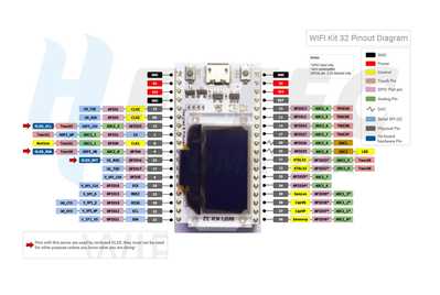
"The quickest way to do this is by holding pin 5 (on the Heltec) high for 10 seconds, until you see it reboot. (Use a temporary jumper between the 3.3v pin and pin 5)."
Is there an image, video, diagram, anything as to what this process looks like? Do I supply power to the board and short out pin 5 by connecting it directly to the 3.3V? Do I run a sketch that simply has pin5 set to HIGH for 10000?
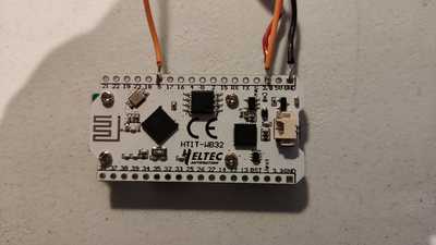
Do I do what's in the image below?
Any help on this would be great.
@markzagit YES, apply power, connect jumper from 3.3V to Pin 5 for 10 seconds.
First computer 1959. Retired from my own computer company 2004.
Hardware - Expert in 1401, and 360, fairly knowledge in PC plus numerous MPU's and MCU's
Major Languages - Machine language, 360 Macro Assembler, Intel Assembler, PL/I and PL1, Pascal, Basic, C plus numerous job control and scripting languages.
Sure you can learn to be a programmer, it will take the same amount of time for me to learn to be a Doctor.
@ronalex4203 Super....
Fantastic. Thanks. I shall give this a go.
I feel a weight has been lifted....
Actually you probably can (and should) eliminate the battery, as the ESP32 will be powered by the USB connection to the computer.
In that case, just remove the battery, the other connection is fine. The 3V3 pin will become a 3.3-volt output when it is power by USB, you can confirm this with a multimeter first if you wish.
😎
Bill
"Never trust a computer you can’t throw out a window." — Steve Wozniak
OK, the first time I did it, nothing happened. But I went back to the flash download tool and tried to load the new program. No joy.
I reloaded the old program and it worked OK. So at least the board works.
So I went back to reflash, and when I connected everything up, it just started the board but no resetting.
Below is the image of my board, also the actual wires I have soldered for the jump. Is pin 5 actually the correct one to jump to? It has a RST pin next to the other side's 3.3V?


