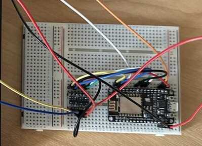
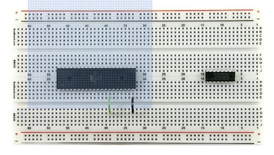
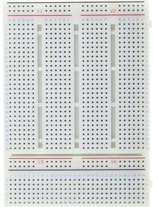
@inq Not 100% sure what you are looking for, but maybe one of these helps
First computer 1959. Retired from my own computer company 2004.
Hardware - Expert in 1401, and 360, fairly knowledge in PC plus numerous MPU's and MCU's
Major Languages - Machine language, 360 Macro Assembler, Intel Assembler, PL/I and PL1, Pascal, Basic, C plus numerous job control and scripting languages.
Sure you can learn to be a programmer, it will take the same amount of time for me to learn to be a Doctor.
@inq Not 100% sure what you are looking for, but maybe one of these helps
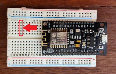
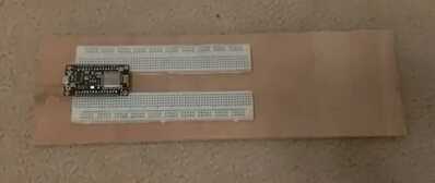
Doesn't look like those are any better. Every breadboard I've seen has only 5 rows. Here is the NodeMCU on one. Note: There are no pins to the sides to actually place wires.
@thephilnewman , looks like it has two rows available on each side. His has six rows.
3 lines of code = InqPortal = Complete IoT, App, Web Server w/ GUI Admin Client, WiFi Manager, Drag & Drop File Manager, OTA, Performance Metrics, Web Socket Comms, Easy App API, All running on ESP8266...
Even usable on ESP-01S - Quickest Start Guide
@davee thanks ever so much, I may try and start the perf board job today, I will post a picture when its done. Just one question, you have got two resistors and two capacitors across the limit switches what voltage do the capacitors have to be? and also what are they there for? I am planninning on putting four limit switches on the unit two at the top and two at the bottom so four in total, so a limit switch at the top on both sides and a limit switch at the bottom on both sides. so will they need the same as well? the two limit switches on each side will be in series and both normally closed.
Cheers Phil
Hi @thephilnewman..I've been following your thread on your train elevator with some interest..I did notice that @davee has provided you with a nice schematic of how to interface your controller to your DM860H driver. Your question of what the capacitors across the limit witches were for and what values and voltage rating were, is a valid question, so I thought I might try to answer them. Firstly, the capacitors are for de-bouncing the switch contacts. They are in a low pass filter configuration for passive first order. The values can be any value of 10 nF to .1 uf and are ceramic type, which are made to withstand voltages of up to 2,000 volts.. they are non-polarized, small, and mostly very cheap! lol
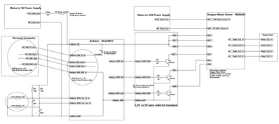
By the way, in @davee schematic, C2 is connected to R4 as in the following modified drawing:
Good luck with your project..looking forward to seeing how you progress toward your goal of making it a reality.
kind regards,
LouisR
LouisR
Hi @thephilnewman,
Postsript Note: Once again it has taken me so long to write my sermon, another kind and observant forum member has posted and the messages have crossed in the post. There are overlaps, but I don't think there any contradictions, so apart from this note, I won't change my script. Thanks to @inst-tech for spotting my mistake in the bottom left corner of the drawing.
One very minor clarification to @inst_tech's contribution re "which are made to withstand voltages of up to 2,000 volts..".
I have seen ceramic capacitors with voltage ratings circa 2kV (coloured light blue?) on AliExpress, and if you have these, I would expect them to function as described. I actually had physically smaller, circular devices, typically light brown in colour, whose voltage ratings are not always stated, but when stated, 50V rating is usually claimed for all but the largest capacitance values that may be down to 16V. These also should be fine for the intended application, and maybe cheaper ... I think I bought a few hundred covering a range of values for the equivalent of a dollar or two.
------------------
The capacitors help to prevent switch bounce problems confusing a program; it is possible to argue they are not neccesary, can be simuated in software, etc., but if you have a pack of capacitors they can be less than a penny each, so I just fit and forget. As for voltage rating, they just need to be above the highest voltage they will experience, which is 3.3V with the NodeMCU. The cheapest ceramic discs (with wires) or surface mount (1206, 805, etc.) will easily meet 3.3V/5V voltages for most processors. The value isn't normally critical either .. something in the 10nF to 100nF should be fine.
-----
I just put two limit switches on the diagram as a 'token' minimum. Increase to as many as you wish, including user 'push buttons' or 'toggles', just remembering to allocate a GPIO pin on the NodeMCU for each one. Putting two or more switches in series (or parallel) can sometimes be a good idea, but bear in mind, it can make it difficult to figure out which one is 'activated'.
e.g. some cars have a single dashboard light to indicate a door is open ... the 'posher' cars have a different light for each door, and save you opening and closing 5 doors just to find the one that is not quite shut, which by chance is usually the last one. If you have sufficient GPIO pins, I generally recommend you only have one switch per GPIO.
--
However, for any such 'rule', there will be exceptions. e.g. you might have one or more safety devices, like limit switches, which should never be close to being actuated in normal operation. In this case, it will probably be obvious which is actuated, unless it is a false alarm.
Depending upon the severity of the consequences of ignoring such safety device actuations, you might use their output to independently stop the system. e.g. in the past, I found a microwave had three switches activated by the door opening ... two stopped the microwave generation, the third blew the power fuse, as a last ditch precaution if the first two failed to do their job.
-------
I looked at the video of the commercial elevator that you posted, and noted that they were using a DC motor, and claimed the use of an optical sensor to ensure it was within (?) 0.01 mm, in spite of the chains stretching. I am guessing your screw threads are unlikely to be significantly compressed or stretched, and providing the motors are adequately powered and controlled, the stepping action determines the position, but I guess some kind of sensor to ensure it was correctly aligned, before moving the trains would be a 'nice touch', as well as a useful diagnosis tool.
-----
I also noted the 37 (?) way power/data connector contacts to connect to the 'selected level'. Do you have an equivalent system in mind.
------
I can't provide any meaningful data about the size/power of motors you have chosen ... definitely more in @Inq's camp. However, I make an observation from cheap end 3D printers ... one upgrade/standard option is to use two threaded screws for the z-axis, so that the height is actively supported at both ends. There are different ways of driving the two screws, but one choice is to continue to use just one driver, and wire the motors in parallel. Clearly this will halve the current available for each motor, though with DM860H, you might just select a higher current limit, and it assumes that the motors have been manually adjusted for a level gantry, before the motors are powered up, which could be problematic if the weight of the platform is sufficient to cause the threads to rotate when the motor is unpowered. Presently, I have no practical experience of the system, but if you found it difficult to keep level with just one central thread, it might be possible to use just one controller with two motors/threads. An alternate, also used for 3D printers is to have a second threaded rod, but using a toothed belt instead of a second motor.
However, this is only speculation. I know almost nothing about mechanical engineering .. and all of this may be unnecessary.
-------------------
Switch Bounce background information
In case you haven't heard of switch bounce, it is when the contacts of a switch (or relay, etc.) are closing (and sometimes during opening), the 'touch' is often not a single event, but more of a stutter of opening and closing events, typically on the microsecond to millisecond timescale. Because processors can thousands or millions of instructions in a millisecond, it is easy for the processor to respond to each of these events, even though they are intended to be a single event.
The effect of the capacitor is to 'slow down' the voltage rise when the switch opens, so that it takes some time for the voltage to get high enough to be seen as 'high' instead of as 'low', when the switch is closed. Although the exact timing depends on several factors, a rough guide is given by
T = 0.63 * R * C, where T is the time in seconds, R resistance in Ohms, and C capacitance in Farads
So with R = 10 kOhms, C = 10 nF, T = 0.63 * 10^4 * 10^-8 = 63 microseconds
increasing C to 100nF, makes this 0.63 milliseconds
For the cheap push button switches, 10nF seems to do the trick, though one might choose a higher value if 'two' clicks would be very troublesome to the user. If you are designing something like the switches on a gamepad, where the user is repeatedly pressing the switches etc., some experimentation with the capacitor value might be desirable.
If the switch is the Reset switch for the processor, it is common to use a much larger capacitor, say 10 microFarads, so that during power up, there is plenty of time for the power supply to stabilise, before allowing the processor to start booting. It also debounces the switch, when the user presses it.
---------------------------
Hope this is all clear ... obviously, some of it is just for background information , which I hope you find interesting and maybe helpful at some time.
Best wishes, Dave
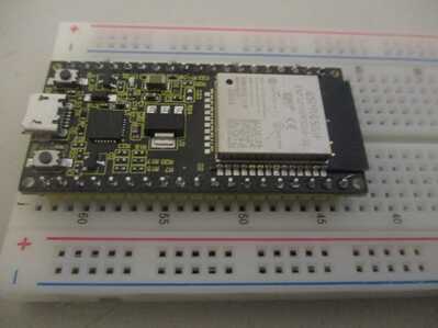
Strange they made the boards that wide. The esp32 board I have (and I see some esp8266 boards) are not that wide.
My esp32 board,
One uTube solution,
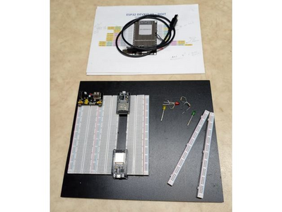
@inq Look carefully at the picture attached, I got this idea from one of Bill's videos as I had esp32's that also would not allow access to the pins, that first (I think) board does as you can see in the picture. All my stuff is either being delivered late or is stolen (and I will retire even from hobby stuff) but if it shows up I will take a picture with a NODEMCU inserted.
First computer 1959. Retired from my own computer company 2004.
Hardware - Expert in 1401, and 360, fairly knowledge in PC plus numerous MPU's and MCU's
Major Languages - Machine language, 360 Macro Assembler, Intel Assembler, PL/I and PL1, Pascal, Basic, C plus numerous job control and scripting languages.
Sure you can learn to be a programmer, it will take the same amount of time for me to learn to be a Doctor.
@inq that took me for ever to find but here it is! I bought this board in a kit many years ago now, and I think it came from a company called Marlins, but I dont think they exist any longer. If your searching for it in the USA look for part number SAD 01.
Cheers Phil
My order for a few of the breadboards is in. RS are probably wondering why they have a glut of orders today. 😎
@robotbuilder This is what I use for ESP32 boards. See other pictures in Thingiverse link https://www.thingiverse.com/thing:5265789
RCC1
@davee I only seem to be able to find the capacitors at 50volts is this okay?
Cheers Phil
@davee please ignore that last comment about the 50volt capacitors I re read what you have written and they are now on order, I will stick to having the two switches in series as they are only overtravel switches and a safety feature at the top and the bottom of each lead screw, I am going to be getting another of the DM860H controllers for the other end of the lift and another nema23 stepper to lift that end, so it is actually a mirror image of the end I have already built. I have also ordered a 5 volt usb type power supply as the 10amp monster is a bit ridiculous, and it will be better used for lights or something on the layout at a later date. Is that true about microwave ovens? good idea if it is I suppose! I will post a photo of the board when its all soldered up.
Cheers Phil
Hi Ron @zander,
Re: I assume that is a 'better' solution than a store bought level shifter.
The schematic is really a summary of several posts for @thephilnewman's benfit .. dating back to suggestions of using voltage converters between @inq and @thephilnewman
My comment at the time was that I didn't know if the commercial boards would work ...
My concerns are:
- Different boards have different circuits ... some only have a pair of resistors, intended for reducing 5V logic levels to 3.3V logic levels. Whilst some suppliers like Adafruit carefully document their product, so that someone with sufficient electronic knowledge can decide if they will work, many come directly or indirectly from China with just a photograph if you are lucky.
- Perhaps the 'best known' circuit originates from a technical note published by Philips some years ago, for the sole purpose of allowing two I2Csubsystems, one 3.3V the other 5V, to function as a single system, implying bidirectonal data transfer.
- This requirement of connecting two wired-OR networks with different voltages, is very different from driving an LED. Only after analysing a solution for one of these requirements, is it possible to ascertain if it will be appropriate for the other.
- Other boards, e.g. one using a TI chip, have been mentioned. I am not clear if they are commercially available ... I haven't spotted them for sale in AliExpress, etc.. I suspect the chip drought might also be an issue.
By contrast, the DM860H manual (and others) clearly show, albeit in a somewhat conceptual form, the expected connection system, in both common cathode and common anode forms. This is (and has been for a few decades) the conventional method of driving the LED of an iso-coupler, of which these driver boxes normally use in a set of three.
The conventional approach only requires a general purpose NPN transistor and a resistor per data line, both of which many electronics enthusiasts will have in their spares box, and are available from ebay, Amazon, AliExpress, etc. albeit in packs because of their individual low price. So, I personally do not recommend the 'store bought board' lottery approach, unless you are prepared for a oscilloscope level debugging session and possible failure at the end of it. Stick to the conventional approach.
Please note, I am not categorically saying a store bought board will not work ... only that it might not ... and that even if it is 'capable', depending on other decisions that anyone who hasn't analysed the circuit in detail would not be aware, it can still fail. For at least some boards, at best, it will always compromise the voltage and current waveforms, which will make it a less robust solution.
Best wishes and take care my friend, Dave
Hi @thephilnewman,
Good, I look forward to seeing the photos.
As for the microwave, I don't know how common it is with microwaves ... I have only fixed two or three, since they have a vicious power supply in them, so I minimise contact to those within the family, but it certainly applied to one made maybe 20 years ago, that was being awkward.
However, I can confirm that for the design of safety critical equipment, it is common to require at least two independent and dissimilar (e.g. using different types of parts) circuits to 'agree' before allowing a potentially dangerous process to start or continue. The implication (grossly oversimplifying the detail and theory) is that if the failure rate of each circuit is (say) 1 in a million, then the chance of two dissimilar circuits having a failure at the same time is 1 in a million million, ie 1 in a trillion.
However, if the both circuits were the same design, then a design failure could be common to both, and having two of them was no better than one .. hence the need for dissimilarity for the safest result.
Plus, if failures are not actively checked for during the life of a product, if one circuit fails (say) soon after manufacture, but is not spotted and replaced, then for the rest of the life of that item, there is only one active safety system.
Probably an over the top discussion for model railway, but sometimes it helps to consider the kind of discussions that must be happening on full-sized railways -- or at least, I hope they are!
Best wishes, Dave
@inq that took me for ever to find but here it is! I bought this board in a kit many years ago now, and I think it came from a company called Marlins, but I dont think they exist any longer. If your searching for it in the USA look for part number SAD 01.
Cheers Phil
Phil, thank you.
Everyone else. Yes, I know how to use more than one breadboard and I usually do for myself. But it is also why I prefer the WeMos that is narrower.
However, I buy in quantities when I give a class on Arduino type electronics and I prefer the NodeMCU so people have more pins for their future projects and I don't want to have to buy two breadboards for every student and I'm not going to run them across the table saw to cut them in two. Until Phil's post, I was beginning to think they didn't exist. His is perfect allowing more components for more extensive projects is a bonus. PERFECT!
Now that I have a name and a model, hopefully I can find them over here.
VBR,
Inq
EDIT: They must be made in England. Amazon, AliExpress, Banggood, eBay... no one had them. Went to your site and it said, "Because of tax situation, we ask that you buy from our US site." I went to the link provided and guess what... that product is not offered from the American site. And at $15 a pop plus shipping from England, this triples price of a student kit. I'll have to continue my search.
3 lines of code = InqPortal = Complete IoT, App, Web Server w/ GUI Admin Client, WiFi Manager, Drag & Drop File Manager, OTA, Performance Metrics, Web Socket Comms, Easy App API, All running on ESP8266...
Even usable on ESP-01S - Quickest Start Guide
@davee that last paragraph really made me laugh! Dont worry there have been a few incendiary happenings in the train room due to "cock ups" I have learnt it doesn't need a lot of volts to make it melt! I had a short on the track in the early days and there was a loco sitting on the track, I could hear something buzzing, but ignoring it I went in for my tea, after tea I went back to find the buzzing had stopped and the locomotive was now welded to the track, not really a laughing matter that loco cost me over £300.00. I learnt a very hard lesson that day.
Cheers Phil

