Hi everyone! I am new to the workshop. I am an ME with advanced degrees in biomedical engineering so I have a lot of theory, but very little actual knowhow when it comes to designing electronics. I was injured in an accident 7 years ago and am paralyzed from the chest down. Now it's time for me to put all that schooling into helping people and build a 16-channel Functional Electrical Stimulation (FES) device. FES injects very low current via surface electrodes through your skin into your nerves to control your muscles. For FES you need to control the current amplitude (0-140 mA), pulse width (0-1 ms), and pulse frequency (0-300 Hz) of the output. I am planning to use four 3.7 V lithium-ion batteries as my source due to their long battery life and quick charging capability. I have kicked around a bunch of ideas like using op-amps, boost converters, etc. Based on my research so far, I think I could use a boost converter with a PID controller that controls the current for each pulse using PWM. I need a specific sine-like squared-off waveform output current that alternates between positive and negative with the same limits as above and I really need to be able to specify the shape of the curve in real-time. I know how to design current limiters and use a DC block for safety, but I just don't know what components I need to control the 3 parameters above or create the custom output waveform. I need some advice from people with more experience. I want to use a Pi 4 for balance calculations and an Arduino for the microcontroller (or something similar). I would be very grateful for any advice you can give me.
There are people on here that probably can help you. I personally am more software oriented and unfortunately, I don't know a way to regulate current except via regulating the voltage through a known resistance. Since the skin/body is not a known resistance, I'm at a loss. The more hardware oriented here, probably can help you, but I think there will be some concern about liability and hurting someone. In the past things that like...
... have people looking for their lawyer.
I find your project very interesting and will be subscribing.
I want to use a Pi 4 for balance calculations and an Arduino for the microcontroller (or something similar). I would be very grateful for any advice you can give me.
Out of curiosity... how intense are the calculations? Short of solving for many simultaneous differential equations or FFT, even an Arduino can do quite intensive calculations. If you're wanting to have some kind of wireless connectivity (Bluetooth or WiFi) an ESP8266 or ESP32 has even more memory (4 to 16MB) for data and 80, 160 and 240MHz clock speeds. It would greatly reduce your overhead having to create some communications between the Pi 4 and Arduino. Just a thought.
3 lines of code = InqPortal = Complete IoT, App, Web Server w/ GUI Admin Client, WiFi Manager, Drag & Drop File Manager, OTA, Performance Metrics, Web Socket Comms, Easy App API, All running on ESP8266...
Even usable on ESP-01S - Quickest Start Guide
@engineerj This sounds like a really interesting project, but as @inq has already said, the legal liabilities are not something I am comfortable with. Also, it sounds like very specialized knowledge is needed and I do not have that. I too will subscribe out of curiosity.
First computer 1959. Retired from my own computer company 2004.
Hardware - Expert in 1401, and 360, fairly knowledge in PC plus numerous MPU's and MCU's
Major Languages - Machine language, 360 Macro Assembler, Intel Assembler, PL/I and PL1, Pascal, Basic, C plus numerous job control and scripting languages.
Sure you can learn to be a programmer, it will take the same amount of time for me to learn to be a Doctor.
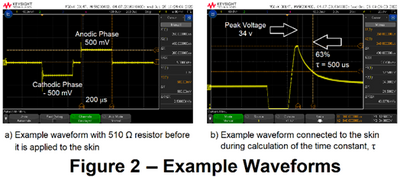
@inq. I appreciate the support. We usually model the skin with around 10 kΩ of resistance. I attached a figure showing the biphasic waveform for an FES device I was working with (on a 500 Ω resistor and on the skin) to get paralyzed hands to move. It is Arduino based but is limited to only 16 mA and is not powerful enough for legs. You can see in the second figure that your skin acts like a capacitor.
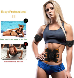
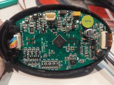
I have 5 yrs of experience working with FES on people, but I have found that universities are more interested in perpetually testing than actually building a commercial device. The FDA puts out guidelines for FES devices. It is just a chart to help you make sure you are safe. It does not require approval before use. That ab device in your post is a good example of FES. Here is the inside of my ab belt controller (it has 2 channels with similar specs to what I need, but you can't change them):
I didn't think it was ethical for me to post questions without telling people what my project was for, but all electrical projects involve safety risks so I hope that people will try to help. I'm not asking for someone to design it. I just want to have some idea what direction to go. Anything I build will be thoroughly tested on the oscilloscope before using it. I am creating a model in MATLAB Simulink right now to see if I can figure it out. I look forward to getting more comments.
Hi @engineerj
I just calculated the necessary Voltage (Ohms law is the secret) to drive 140mA over 10k skin resistance. The voltage required is 1.4 kV ?!?
And >60mA across your heart is lethal.
I think it should be micro Amps (uA)
Rule of Thumb in hardware/software engineering:
From the estimated time to complete a project you need:
5% for the engineering itself
95% securing everything against any strange idea users can have
and the remaining
150% for finding and fixing bugs that you thought never could happen
@hzulu The hydrogel used on the electrodes lowers the skin resistance down to about 1 kΩ. This makes the voltage around 143 V which is about 20 W of power. A compliance voltage of 200 V or less is very common. Compare this to my FES bike specs:
This is from an RT-300 FES bike I have from restorative-therapies. You can see this matches the specs on the screen and the nameplate. Each channel has 2 electrodes, one to input current and one to remove it so it is not going across your heart. They have a large surface area, so the charge density is pretty low too. FES has been around since the first commercial device came out in 1984 (Parastep). The problem is these devices are all proprietary, and you can't program them except to adjust the intensity. No new devices like Parastep have entered the market since the late 90s, and they are all clinical-use devices meant to use with parallel bars or a harness over a very short distance. I have a master's degree in biomedical engineering specializing in neural interfaces like FES, and I am working on my PhD doing research with ultrasound to stimulate the dorsal root ganglia to facilitate walking. I have always used equipment that is not portable and very expensive in the lab. I need a portable, programmable device to do what I really want, which is to walk and go about my daily life in a more normal manner.
Wow! a pretty cool idea to drive your legs muscles with electrodes controlled by a program and to be able to walk or to ride a bicycle
Although, I think it's quite a challenge to keep all parameters under control (sense of balance, feedback from muscle strength, tiredness and a million and one other things...) to make a human stand upright and walk, it's a very interesting area of research.
Let's make one step at the time - back to your problem.
How high do you estimate the total power requirements when you orchestrate 16 channels for a particular movement of legs/hands.
How long do you want the batteries last at the given power?
For the the first shot of desigh I'd suggest the following sequence:
- Build a boost converter, capable of 200V and the total power requirement
- Build a programmable switching current source for each channel, again capable of max. 200V input voltage. I found an application note from Microhip, which I think, can be adapted to your requirements
https://ww1.microchip.com/downloads/en/DeviceDoc/51798a.pdf
- Build an H-Bridge for each channel to make the output "AC" and impose the
switching pattern.
- For individually controlling all channels, I think one Arduino Nano (or similar) per channel is necessary to do all the fine grained realtime stuff.
- Just in case you are very brave you could use the new Microchip Polarfire FPGA with integrated CPU Core, to do channel timing and current control in hardware and supervision in software
Rule of Thumb in hardware/software engineering:
From the estimated time to complete a project you need:
5% for the engineering itself
95% securing everything against any strange idea users can have
and the remaining
150% for finding and fixing bugs that you thought never could happen
Hi @engineerj & (@inq @hzulu @zander),
As others have said, and it appears you are aware, this is potentially a dangerous, and even lethal project. Whilst it is interesting to hear of your qualifications etc., of course the Internet provides enough anonymity to enable Dr Frankstein to masquerade as Mary Poppins, let alone knowing that degrees do not always equate proficiency. So whilst I don't mind trying to assist people, particularly with an interesting or potentially useful project, it is only on the basis that 100% of the responsibility of the consequences of any such advice rests with the person who acts upon it, and absolutely none of the responsibility is mine. This applies, regardless of whether the advice I gave is good, bad, useful, useless, right, wrong, etc.
So far as I am concerned, any advice really applies to putting a few dollars worth of electronics together, with the worst risk being those electronics emitting some magic smoke. Any electrical connection of those electronics and humans is 100% your choice, decision and responsibiity.
------------------
So on that basis...I am not sure if I can provide complete answers, but I might suggest that the specification of what is required is not very clear to me. In many cases, and I suspect this is one of those cases, the lack of an understandable specification can be more limiting and difficult to solve, than finding an electrical circuit to solve the eventual problem. Furthermore, I think if you can produce a specification that an electronic engineer can understand, without having to consider the biological consequences, it greatly increases the number of potential advisors. Of course, you probably have more information, but not yet had the opportunity to present it ...
In particular, I think you need a 'realistic model' of what 'electrical' load the 'human' will present to the circuit and you also need to specify in terms of both voltage and current waveforms, is likely to be required to achieve your aims. I can see you have presented a couple of voltage waveforms, which is a start, but I have the impression they are what you have available, rather than what you need. And I think you need a more realistic 'human body' load ... preferably as an electronic circuit, but maybe we can develop that if you have some relevant data ... I am pretty sure a simple resistor is not enough...
And whilst I realise, part of the project is to produce something with adjustable parameters, it is necessary to determine the likely range of each of these adjustments, and to know something of how adjusting a parameter will affect the other requirements, etc.
This partly appears to be a project to develop a 'better mousetrap', so as a staring point, you may be able to collect some useful data using the presently available equipment, remembering to annotate it with some estimates as to how it needs to be extended, adjusted, etc. for your 'better mousetrap'.
------
Does this make sense, seem reasonable and a practical way forward? Feel free to question anything!!
Don't worry about producing a perfect specification in one go .. present what you know, etc., and hopefully we can move forward in small steps. Sorry, if this feels like a step backward, when you were looking for a simple answer, but I think it is the best, and probably only realistic way forward.
Best wishes and good luck with your project, Dave
@engineerj FYI @davee Maybe I am way out in left field here, but a couple thoughts are first how is this different from the Dr Ho gizmo, or TENS device. Secondly, this is nothing new AFAIK and I would be completely shocked if you have invented a device to make the crippled walk again. I am sure I am misunderstanding, but I suspect many others are as well so you need to address that.
First computer 1959. Retired from my own computer company 2004.
Hardware - Expert in 1401, and 360, fairly knowledge in PC plus numerous MPU's and MCU's
Major Languages - Machine language, 360 Macro Assembler, Intel Assembler, PL/I and PL1, Pascal, Basic, C plus numerous job control and scripting languages.
Sure you can learn to be a programmer, it will take the same amount of time for me to learn to be a Doctor.
@engineerj
Sorry, I made a mistake by suggesting you a single big power supply for all channels. There would be cross current from one channel to the other. Potentially across the heart, when you put one channel to the left arm and annother channel to the right arm.
Actually you need an electrically isolated supply for each channel. This also involves individual optocoupled control lines for each channels current source- and H-bridge controls.
Rule of Thumb in hardware/software engineering:
From the estimated time to complete a project you need:
5% for the engineering itself
95% securing everything against any strange idea users can have
and the remaining
150% for finding and fixing bugs that you thought never could happen
@davee I really appreciate your feedback, and I think it is healthy to be skeptical on the internet so I wrote a crash course in how this works and then I have some comments on my progress below.
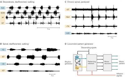
There have been huge breakthroughs in our understanding of how our bodies function in the last 20 years, but since "the walking problem has been solved" mentality has been in place since the 90s, not much has been done commercially. Walking in mammals is actually controlled mainly by spinal cord circuits, and in 4-legged animals, experiments from the 1950s showed that you could actually sever their spinal cord at the brain stem, and they could still walk once you get them started.
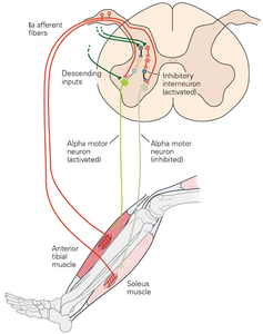
(Human central pattern generator circuitry from the spinal cord to the leg and intercellular recordings of motor units to various muscles during walking)
Humans are a little trickier, but if you stimulate the peroneal nerve, near your knee, it can start that central pattern generator that will alternately lift each leg and control the flexor/extensor muscles. Your brain just controls start/stop (descending input in the figure) and rate of walking, as well as telling you to lift your leg over an object. The muscles shown in the figure are the ones you use for standing balance as well. The inhibitory interneuron will fire to control the flexor/extensor muscles so that you don't push and pull simultaneously but also maintains the tension on the opposite muscle so it doesn't get damaged. Your brain gets proprioceptive feedback in the form of position, force, and velocity information from the muscle spindles, and Golgi tendon organs. That is why I have to incorporate IMU's for control.
I did some design work and watched YouTube videos all weekend on Buck/Boost Converters with feedback control, PWM, etc. and ran some simulations in Simulink to see what is possible. What I found was what you alluded to, that the converter is too slow to meet the 100 ms timing that is really needed to control your muscles. You are also correct that the specs I came up with are based on the stimboxes we used in my neurorobotics classes and what is listed on the RT-60 controller on my FES bike. One of the things I want to do is hook up EMG to the legs of an undergrad student that is helping me that is about my size and record each muscle when he sits/stands, and walks at various speeds to record the frequency and pulse width for each action. If I can get enough recordings I can use machine learning to help in controlling the device. I have done extensive work with machine learning using Utah Slanted Electrod Array (USEA) data from hand experiments here at the U. I have to get going to the lab, but I will try to post more specs tonight.
Also, some people have sent me private messages, which I really appreciate the support. I cannot respond to them until I have 10 approved posts. Just FYI.
Thanks to everyone for your help.
Hi @engineerj,
Good to hear back from you ... as I tried to say, I am not judging your experience, etc. .. I was only pointing out that I couldn't judge it from afar, anyway ... just please accept you are 100% responsible for what you do ... even if I make mistakes in something I suggest.
---------
I don't know anything about this biological systems, though I had heard that previous ideas that the spinal cord was only a kind of 'coax cable' to transmit brain messages, was being revised to think of more as part of the thought processing system, so the parts of your description I can understand makes sense. Unfortunately, some of the detail needs further explanation for me to comprehend it, though that may not be too important.
------
Please remember I, and I guess other forum readers, will not recognise acronyms that are 'private' to the subject of your studies, so please add at least the full version, and maybe a brief explanation, when it isn't obvious. Otherwise, we need to spend hours with Google trying to decipher some of them. 🤨
For example .. EMG, what is it? what conditions? etc. And FES? I know what a bike is, but FES bike?
-------
I previously mentioned that eventually you will need a specification of the electrical stimuli you wish to create ... as you are now pointing out this involves time, as well as voltage and current.
Are you also measuring 'fully-able' subjects to try to see what messages their body is sending, to get an idea what might be needed?
---------
Best wishes, Dave
Hi Ron @zander,
Not my specialty field either Ron, but I think it is pretty clear this is much more 'intense' and also much more specific than the various TENS machines on open sale, which largely seem to be trying to provide pain relief.
It is actually trying to replace some of the messages that would be sent from the brain if the spinal cord had not been severed, in a manner to 'fool' the legs of his subject to think the brain has been reconnected, and hence enable the person to walk etc.
But I'll leave @engineerj to give the definitive scope and aims of the study.
Best wishes, Dave
ps I hope you are feeling better.
@davee I am really unsure what is going on here. Are we all involved in what will end up as a NOBEL prize project?
Some good days, some not so good.
First computer 1959. Retired from my own computer company 2004.
Hardware - Expert in 1401, and 360, fairly knowledge in PC plus numerous MPU's and MCU's
Major Languages - Machine language, 360 Macro Assembler, Intel Assembler, PL/I and PL1, Pascal, Basic, C plus numerous job control and scripting languages.
Sure you can learn to be a programmer, it will take the same amount of time for me to learn to be a Doctor.
I'm not sure I can contribute anything to moving the yard stick (or leg) but my chronic and acute Inquisitiveness bordering on Tourette's forces me ask questions. Since the topic is so far out of my comfort zone, I continuously look for corollaries in my world. Therefore...
Walking in mammals is actually controlled mainly by spinal cord circuits, and in 4-legged animals, experiments from the 1950s showed that you could actually sever their spinal cord at the brain stem, and they could still walk once you get them started.
...
The muscles shown in the figure are the ones you use for standing balance as well.
...
Your brain gets proprioceptive feedback in the form of position, force, and velocity information from the muscle spindles, and Golgi tendon organs. That is why I have to incorporate IMU's for control.
I'm am very curious about this series of excerpts. In subsequent sections, you mention about the brain (via the spinal chord) still controls the "global" controls like obstacle avoidance, deciding when, and how fast, etc. If the brain link is severed 😫 what are these theoreticians proposing that controls the simple balancing aspect of walking? IOW... what is IMU controlling the body's balance? I would have thought the only human sensory organ capable of that kind of feedback is the inner-ear... thus requiring the spinal chord.
In particular, I think you need a 'realistic model' of what 'electrical' load the 'human' will present to the circuit and you also need to specify in terms of both voltage and current waveforms, is likely to be required to achieve your aims.
...
... I am pretty sure a simple resistor is not enough...
Spot On! @davee
With my limited EE hardware experience... my simplistic model V=IR (I have a hammer, the world is my nail). In wiring, resistance is proportional to length and inversely with cross-sectional area. Then there's material. Be it upper leg or lower leg muscle, a biker's muscle, a couch potato muscle or an atrophied muscle. You did mention the algorithm and hardware needs to be adjustable. A barn-door comes to mind.
Just for S&G, I used my ohm meter on every settings from 200 to 2MΩ range across the length of my calf muscle. I didn't get any reading at any setting. I guess what I'm getting at, it seems the 10kΩ mention doesn't seem to be applicable. The skin, is merely an insulation, its the muscle that is the conductor of choice. Jell just makes the contact spot of less resistance and is only that infinitesimal depth that is improved.
Which brings up another quandary to me. When I see pictures of the "pads" on the muscles. Even the one you presented above. They're right next to each other. I would think the current is only going to take the path of least resistance and thus only flow between the two pads. It would seem to me they need to be at each end of the muscle being stimulated. If not, it would seem the rest of the muscle between pad and tendon would atrophy.
What I found was what you alluded to, that the converter is too slow to meet the 100 ms timing that is really needed to control your muscles.
Now, back to something more related to your current (both meanings) problem. I didn't see where someone mentioned this. Would someone care to elaborate? I know this is not a limitation of the MPU. I routinely do feedback projects in the sub-10ms range. What converter was the problem? Instead of using an off-the-shelf converter (Buck, etc) wouldn't some kind of Mosfet combined with a shunt or hall-effect circuit using PWM to vary the voltage be quick enough? The hardware details are way outside my hardware abilities!
This is a really interesting project!
VBR,
Inq
3 lines of code = InqPortal = Complete IoT, App, Web Server w/ GUI Admin Client, WiFi Manager, Drag & Drop File Manager, OTA, Performance Metrics, Web Socket Comms, Easy App API, All running on ESP8266...
Even usable on ESP-01S - Quickest Start Guide

