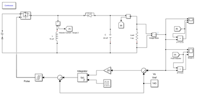
Hi everyone. I am trying to build a boost converter that can go from 12-48 V (not sure of the input voltage I need to use) and outputs up to 200 V. I ran a model in MATLAB's Simulink, and although the current output of the converter is pretty low, the inductor current is crazy high. Here is my model:
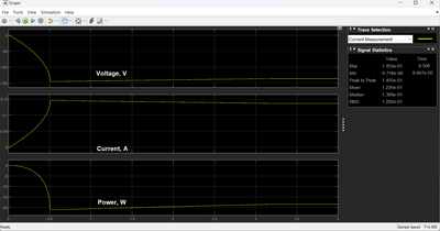
Here is the profile for the output, which is currently set at 143 V.
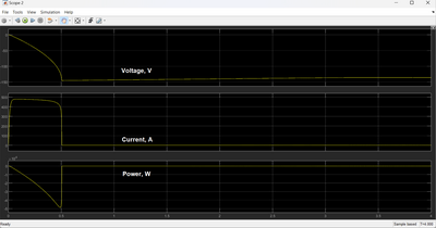
You can see that the current output is very small at around 140 mA. Then you look at the graph for the inductor, and you get something much different.
The inductor current is at like 450 A! Is that real? That doesn't seem realistic to me at all, but I don't really have any practical experience with these circuits. The voltage source in the model is 48 V (voltage is negative in the graph). Why is it ramping up from 0 V when the source is 48 V? It looks like it is taking 0.5 seconds just to get to the supply voltage. I don't understand. I found a website for determining on-time cycles to prevent saturation, and it said that the cycle time for a 10 A, 1 mH inductor was 208 microseconds at 48 V, but at 7 V, where the current peaks, it was 1.429 ms. I have seen converters that can go from 12 V to 160 V, so I know it is possible. Is the model just wrong, or am I missing something important?
Update: I reran the model but put more inductors in parallel, and it significantly dropped the current across each inductor. Then I decided to check the capacitors and found out they had the same problem, so I put more capacitors in series. Each capacitor saw an initial spike up to the 480 A range, but only until it was charged. After that, it dropped the current down to a max of about 1 A. I don't know if there is a way to keep the current down in them or not.
Perhaps an inrush current limiter.
Anything seems possible when you don't know what you're talking about.
Hi @engineerj,
Simulators are magic ... they can handle millions of volts and amps without breaking a sweat.
Real parts tend more towards to display magic smoke on much lower voltages and currents. 😟
An inductor handling 480 A at appreciable voltages, is the sort of situation I would not want to be in the same room ... let alone connected to it!
And 40,000 microFarad capacitors handling those kind of voltages and currents are even more scary.
So I agree with you, "the inductor current is crazy high" ... at least in the real world.
---------
Designing switched mode power supplies are a mixture of art and science on a good day.
On a bad day they smoke and/or explode, and with much lower currents and voltages than your simulation was suggesting.
I suggest you look start by looking for designs which are close to what you want, and maybe think about modifying there charateristics, hopefully doing little more than a resistor change or similar, but maybe more.
And whilst Simulink is a powerful tool when aimed at the right problem, but for an electronic circuit, I would generally look towards a simulator designed for electronics.
LTSpice, free download from Analog Devices, is a good starting option, albeit not the only one available.
Best wishes, Dave
@engineerj @davee Let me add my concern to Dave's. 480A is very dangerous to say the least.
First computer 1959. Retired from my own computer company 2004.
Hardware - Expert in 1401, and 360, fairly knowledge in PC plus numerous MPU's and MCU's
Major Languages - Machine language, 360 Macro Assembler, Intel Assembler, PL/I and PL1, Pascal, Basic, C plus numerous job control and scripting languages.
My personal scorecard is now 1 PC hardware fix (circa 1982), 1 open source fix (at age 82), and 2 zero day bugs in a major OS.
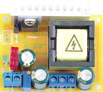
@davee Thanks for the input. I took your advice and bought this on Amazon.
I will run some tests on it so I can learn how it works. It is designed for an output of 45-390 V, so I am hoping that it won't blow up immediately since I only need 200 V at 0.140 mA. It says it can take 10-32 V as an input with a 5 A max current. I was planning to use four 18650 batteries to power it at 14.8 V. It looks like they can provide up to 2 A. Does that seem reasonable? I have no experience working with inductors or capacitors outside of computer models. I took an electronics for non-electrical engineers class (I was an ME) that had a lab back in 1992, and we built simple timer circuits and stuff, and I don't remember much about it. We just did what the lab instructions said, so I didn't have to worry about blowing something up. So, any tips you have would be appreciated.
Hi @engineerj,
Hopefully it will be helpful start and will be a more realistic starting point than your Simulink model.
I don't know the device, so I started a quick search in UK Amazon and came up with:
//www.amazon.co.uk/AEDIKO-Converter-45V-390V-Capacitor-Charging/dp/B0B6G34BB9/ref
which I assume is the same one.
And the advert for it includes:
- Input voltage 32 Volts; Input Current: 5A; Quiescent Current: 15mA;
- Output Voltage: ±45-390V; Output Current: Maximum 0.2A; Output Power: 40W
- Attention:High Voltage Boost Converter module has High Output Voltage, Which is Dangerous to Human and Animals.Please More Careful During Using
To reiterate a theme, the 'Dangerous to Human' part is 100% down to you.
-----------
You should probably start with a risk assessment and put some safety measures in place. I would hope you can get some local help on this, as it realistically needs to be done by someone who can physically see what is happening etc.
I am including a few suggestions to think about, but there will be just as many other things I will not realise or forget, so please just treat it as a starting point for some local discussions.
----------
I can understand why you might want to use battery supply ... please remember Li-Ion batteries can also turn nasty if you mistreat them. Probably unlikely to be harmul from electrocution at just 15V, but from other hazards including exploding, fire and toxic gases. Most obviously, protecting is needed during both charging and discharging.
I'll presume charging will be via suitable and reliable charging device, and not at the same time as the battery is being used.
--
In particular, for both charging and discharging, have an inline fuse, very near to the battery itself so that it will blow if something like the wires from the battery short, and of a value chosen to blow if this converter decides to draw more current than normal.
Aim to have as lower value fuse as you can. Not knowing the characteristics of the power supply it is difficult to suggest precise values, and furthermore European and US fuses are specified in different ways. I would hope it could be less than say 5A 'slo-blow' and would be concerned if it was much higher than this. Obviously it should be below the battery manufacturer's discharge rate limits. Sadly, many Li-ion batteries have specifications that seem to have been written to sell the product, regardless of their implications to the user, so even more care needed here.
--------
Personally, I would also consider making/obtaining a small current limiting circuit for the input to this step up converter, which would act faster than the fuse, but leave the fuse in circuit as an 'if all else fails' backup.
Maybe a linear voltage regulator in current limiting mode. Check out data sheets and app notes for variable linear voltage regulator devices that can deliver at least 5A at 15V or more. Companies like Texas Instruments would be on my look up list.
-----
I presume the small potentiometer on the converter is a voltage adjust, and that you intend to 'dial-up' a fixed voltage to feed some other magic circuits that produce controlled waveforms, yet to be designed.
To protect against an unexpectedly high current demand from the converter output:
a) a low value fuse in series with the output would be a good idea, but I don't how available they are at useful values.
A related possibility is a small value, small wattage resistor with plenty of room around it so it can safely burn out (with a small flame, so avoid flammable plastics nearby) if the current through it increases dramatically. Note small wattage resistors also have limited voltage ratings, so sometimes two or more in series are required. Some resistors are actually specified for this kind of usage, although I don't know how available they are in small off-the-shelf quantities.
As an additional safety precaution I would look at having a device that will trigger if the voltage exceeds a certain value:
b) The voltage regulation function could fail, resulting in a much higher voltage. You may be familiar with zener diodes, which will conduct if the voltage exceeds the 'zener' voltage. The current/power conduction capabilty of Zener diodes is usually too small to 'drag' a power supply output down to safe level, although they can be used to trigger a high current device into conduction ... a circuit known as a 'crowbar'.
e.g. see the discussion on https://www.electronics-notes.com/articles/analogue_circuits/power-supply-electronics/over-voltage-protection.php
Alternately, there are other devices with a roughly Zener like behaviour, that is robust enough to blow a fuse or similar.
e.g. Varistors ... for a start try Littelfuse discussion at https://www.littelfuse.com/products/varistors.aspx
----
It should be apparent, that it is common to have both a) overcurrent protection and b) overvoltage protection, which are expected to operate in a coordinated manner, so that an overvoltage condition will cause the varistor, crowbar, etc. to dramatically increase the current flow, and the overcurrent circuit then breaks the circuit, removing the output voltage.
------------------
Of course this is all 'general background' material, so it will require a good deal of further researching, but I hope ther are some useful suggestions of where to start.
Having a reasonably safe source of your 'high voltage' should be a useful start. Of course, the specification and implementation may change as you get more experience, but that is generally true of the research journey.
Best wishes, Dave
@davee Thanks so much for the info. This is exactly what I need. I have no problem doing research before I start; I just don't always know what questions to ask.
Hi @engineerj ,
Thanks for the kind feedback. But just use my (and everyone else's) suggestions as starting points for your own discovery.
Keep asking questions; make sure you understand and double check the answers. If it doesn't sound right or doesn't make sense, it usually means either you haven't understood it fully, or it is wrong, and sometimes both of these choices. So don't accept what you have been told, be a 'good detective' and keeping looking for more evidence.
There is a lot of misinformation in this world, and electronics suffers in the same way as other more 'obvious' subjects.
Best wishes, Dave


