@davee Hi Guys, Sorry about the acronyms. FES is Functional Electrical Stimulation. It is basically the same as TENS, or NMES devices that are common. The only difference is what it is used for. FES is for functional use (as in moving to build muscle), the others are for pain and rehab. Same device, just different use. My FES bike uses electrodes on my legs while I sit in my wheelchair and it makes my legs peddle the bike. I have a picture of it in one of the earlier posts (RT-300 from restorative-therapies). For one of my design projects, we actually took a TENS unit and hooked it up to some optocouplers to turn it on. We used a recurrent neural network to read the electromyography (EMG) signal coming from the second set of electrodes. When you flexed your arm it would turn it on and bend your arm for you. It was supposed to be a demo of how to help people who lost the use of one arm after a stroke. It had the same parameters that I specified in my original post, but a slightly lower current amplitude (90 mA) because it is for pain not movement.
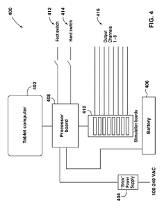
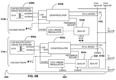
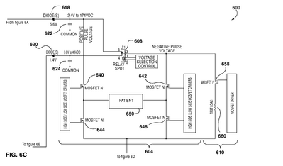
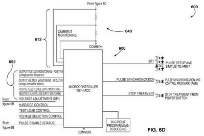
I was trying to find some better specs and I found this FES system design in a 7 year old paper. It is for hands and arms so it has a lower current amplitude.
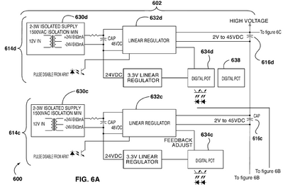
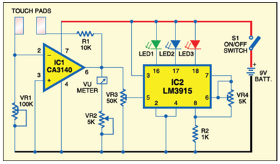
I am not sure what some of the symbols mean though. hzulu thought that each channel would have to be isolated, but this drawing looks like it is using a single power source. I also found this design to measure skin resistance:
I think I would like to build this so that I can get a better idea what the skin resistance is on my legs. I will also post it as a separate post so I can keep track of everything better.
@inq I will try to answer your questions here. And to everyone on this thread, anything you post is just a suggestion. It is my responsibility to verify it is correct and I would never come back and blame anyone. I appreciate everyone's insight.
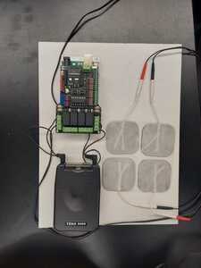
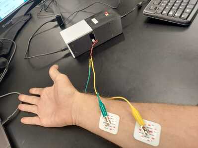
In one of my classes we were using a stimbox which was an arduino wired up where we could control current amplitude (0-16 mA), pulse width, and pulse frequency with MATLAB code. Here is the stimbox setup:
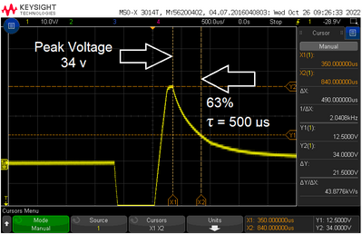
We were just testing the skin so the electrodes are not placed over a specific muscle. Then we ran the signal through the oscilloscope.
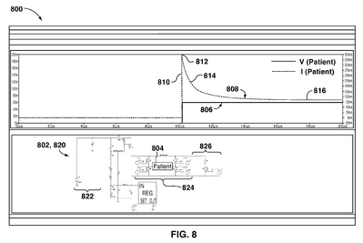
Notice that your skin acts like a capacitor and has resistance (although it is usually talked about in terms of conductance). We ran 2 mA through the skin for this test. So, the max resistance from the figure was R = V/I or R = 34/0.002 = 17kΩ. However, after 5 time constants, it will reach steady state, which looks like about 2.5 v, so R = 2.5/0.002 = 1,250 Ω on your arm after a very short time. I am pretty sure that your legs are about the same. So, I am thinking, if I send out a known current pulse and then measure the voltage after 2.5 ms (5 time constants), I should be able to know the resistance so that I can then get the correct voltage to send a certain amount current. I can't do it every pulse because the pulse width is less than that, but at least for the initial pulse it should work.
I think there is some confusion about how the FES actually works. It is not using electricity to make your muscle move; it is sending enough current into your motor nerve (the nerve that goes into a group of muscle fibers called a motor unit) that it thinks it is receiving a signal from the spinal nerve and propagates the signal to the motor unit. The nervous system is a lot like a microcontroller. It uses pulse width and pulse frequency to determine when to move and how hard. Your brain sends the signal, but your spine decides how many motor units to activate using messages from your brain. A reflex can take about 40 ms because it is just going to the spine and back down, so it automatically lifts your leg if you step on a nail. That's why it seems like you react before you can think about it, because that is what is happening. If you have to think about a specific movement, that can take 100-300 ms depending on how complex it is, because it has to go all the way to your brain, get processed, and be sent back. That is where I got 100 ms from in the previous post. As long as the device is at least as fast as your body would be, then it is fast enough.
This leads into the question about the 2 pads being located so close together. Keep in mind; you are not trying to power the muscles; you are trying to activate the nerves that feed the muscles, so you don't need to have it down the whole muscle.
As far as the balance question you had, where you wonder how a cat could balance without a brain connection, the answer is that it has 4 legs. I don't think a human could balance, without some other computer aid, without a signal from the brain. Your legs will still step without your brain, but on 2 legs, I don't think you would make it very far without falling over.
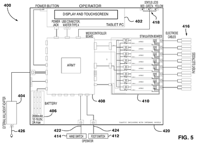
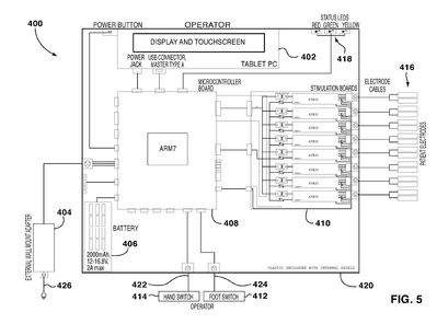
So, I am trying to understand this diagram:
It looks like the power comes in from either a wall transformer or battery at 12 VDC. It then goes directly into the ARM even though the specs for the ARM say 1.8-3.6 V. It has what looks like a PS/2 port (for a mouse?) coming into it. Then it goes out to the "Stim Board" and is again labeled as 12 v. That 12 v then steps up to the compliance voltage of 160 v and goes into an AVR32. It looks like an 8-bit version and not the current 32-bit version based on the shape. There is also some other symbol that is going into the side of the AVR32 that looks like some diodes and MOSFETs? No idea what that does. And then it goes out into a similar PS/2-looking 4-pin female connector with a bunch of wires running in parallel across all the channels. Don't know what that is for either. There are 4 wires going to the 4-pin, but 2 of them branch off between the AVR32 and the 4-pin connector and pick up a 3rd wire from another pin on the AVR32 and seem to connect up to a common wire running across all 8 channels. I would really like to understand this diagram better if anyone understands it. Why do you need an ARM and 8 individual microcontrollers? Is the ARM like the conductor taking in parameters and then telling the AVR32 what to do, and it does the actual PWM control?
Jeff
I think there is some confusion about how the FES actually works. It is not using electricity to make your muscle move; it is sending enough current into your motor nerve (the nerve that goes into a group of muscle fibers called a motor unit)
I know I was confused. I was thinking the muscle was a bundle of wires and needed to put one contact at the ankle and one at the knee to excite all those in between and that they needed more current for the length, area and fat content. 👍
A reflex can take about 40 ms because it is just going to the spine and back down, so it automatically lifts your leg if you step on a nail. That's why it seems like you react before you can think about it, because that is what is happening. If you have to think about a specific movement, that can take 100-300 ms depending on how complex it is, because it has to go all the way to your brain, get processed, and be sent back.
I wouldn't have guessed we're that slow. The lowest end Arduino can blow that away. I'll have to remember that on a robot... Ah... I have 300 ms to before making the decision left or right? And I'll beat the human to the 🍻 😆
So, I am trying to understand this diagram:
I'm not a hardware guy, so I'll defer...
It looks like the power comes in from either a wall transformer or battery at 12 VDC. It then goes directly into the ARM even though the specs for the ARM say 1.8-3.6 V. It has what looks like a PS/2 port (for a mouse?) coming into it.
The diagram says "microcontroller board"... so I'd say that 12V is going directly into a motherboard of sorts and there is a DC-to-DC converters on board to supply the ARM with its preferred voltage. Also, I would not infer just because it has a PS/2 port, that its following any kind of PS/2 port protocol. It might be some proprietary AC adapter brick. ie... Dell was notorious for making bricks that had several wires where the computer had to tell the brick to turn on. Makes them a PITA for us DIY wanting to power our projects. But don't take my word for it, I'm not a hardware guy "Any sufficiently advanced technology is indistinguishable from magic.". So I prefer to think of it as a black magic box. 😉
Why do you need an ARM and 8 individual microcontrollers? Is the ARM like the conductor taking in parameters and then telling the AVR32 what to do, and it does the actual PWM control?
Yes, I know its quite common in robots to segregate chores. Arduino micros handle the direct to steppers, motors, encoders, servos, etc because they only have that duty and do nothing else. Single loop. Where as any "thinking" duties go on a higher processor ARM/RasPi/PC where multi-tasking is going on. The pre-emptive multitasking (CPU time slices... pauses a task here to work on task there) would be a real SNAFU if you tried to drive those steppers, motors. Kind of like your human reflex, spinal chord handling the duties versus the brain thinking about it duties. If we had to think about which muscle to move, we'd never get out of bed.
VBR,
Inq
3 lines of code = InqPortal = Complete IoT, App, Web Server w/ GUI Admin Client, WiFi Manager, Drag & Drop File Manager, OTA, Performance Metrics, Web Socket Comms, Easy App API, All running on ESP8266...
Even usable on ESP-01S - Quickest Start Guide
@inq Thanks for the input. As a software guru, do you know what the address is for on the circuit diagram? On each of the AVR32 chips it says Address 0-7 for the 8 channels. Is it like a boolean that is turning it on or off? It has a dedicated wire going to it with some diodes and transistors (optocoupler?) just upstream.
Jeff
I think you're blurring the distinction between hardware and software. And all this is pure speculation from maybe thirty minutes of thought on your thread. Am I correct that each of those AVR32 units hook to a skin pad electrode (pad)???
The hardware side which is really a guess on my part would have at least two electrical paths to it. It'll need a low voltage / low current logic line running some kind of communications protocol (Serial, SPI, I2C, custom, etc). It'll typically be 3.3 or 5V with current down in the single digit mW range. It'll also need a high power supply that is the voltage/current your pad requires. As I mention in the last post, the AVR32 will likely take abstract commands from the ARM7 brain like: (ZAP at 100 mA, 150V or 10 ms). The ARM will go off and do something else Brainiac like. The AVR32 will calculate the required configuration of the PWM... say things like the pulse frequency and pulse duration. It'll start the process, time it and stop it at the appointed time. The logic level voltage will be used to trigger that Mosfet which in-turn will let the high voltage/current pass to the pad. I can imagine the AVR32 could also take responses from the PAD or secondary sensors and adjust real time for things like the capacitance you mentioned. In this way acting like the "reflex" you mentioned. The ARM7 will get notified, if desired, but, the AVR32 might react directly.
Software on the other hand is even less visible from looking at a schematic. Assuming OOP (Object Oriented Programming) principles are being practiced, I'd make an software object say... AVRClass that exposes that abstract ZAP command as input and it handles all the electrical duties of the AVR32.
The brain (ARM7) would make 8 instances of that and put them in an array. AVRClass[8] channels. Then the brain would orchestrate like...
AVRClass[8] channel;

channel[0].Zap(100, 150, 10);
delay(10);
channel[1].Zap(50, 200,5);
IOW, the brain would just take your voice, dial, button, and zap away merrily possibly taking in other environment input... and thinking deep, AI, taking over the world thoughts. 😋
VBR,
Inq
3 lines of code = InqPortal = Complete IoT, App, Web Server w/ GUI Admin Client, WiFi Manager, Drag & Drop File Manager, OTA, Performance Metrics, Web Socket Comms, Easy App API, All running on ESP8266...
Even usable on ESP-01S - Quickest Start Guide

