I understand your comment fully. It is important to provide sufficient information so someone could even try to help this is true. On the other hand when someone who is posting tries and thinks he has given all the information someone needs it is dreadfull people act annoying by the question or when it lacks the information they need to help you.
I'm trying to say that I might think I give the relevant information but actually I don't and that might be because my lack of understand the problem. Si if I did not give sufficient information in that case that's not because I don;t want or being lazy just because I don;t see the issue.
I think also all the code I have posted above is tooo much information oneneeds to help me with the issue I originally posted.
So to come to my point it would be nice people sometimes don;t get annoyed immediatly. I understand there are people like @Ron said write my project doesn;t work help me....fix it. Offcourse that's not how it work.
Everybody how comes here and people who try to help others do that in their spare time so good information is needed and especially some efford by the OP is needed.
Grtz,
Ray
And to come back to the subject......
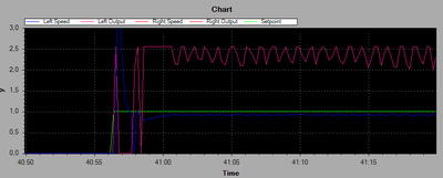
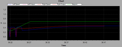
I have come a bit closer to fix my problem. The regulation looks much better. I have discovered that the error depends on my filterweight (this is something which is not in the original code) no one could have known this as the code has been changed during troubleshooting. Also the tutorials helped me but im not there yet. But if the project would work in just one afternoon it would not be fun the process to come to a working project is the fun part.
Below a picture of the progess I made. It will not be the final result but a good step ahead what I want.
Grtz,
Ray
I did not have you in mind when commenting about people not providing the full picture along with their question.
I had ron's comment in mind "So many come here and simply say my thing doesn't work, help me." which didn't apply to your post.
Giving the complete code was fine, it was just too much for me, particularly as I haven't used the WIFI at all in any project and although I played with the PID algorithm I am not an expert in that area. Giving the complete code was better than some out of context snippet of code.
Finding bugs is part of the joy of programming 🙂 I have just finished finding two bugs that were causing a program I am working on now from working. The code looked fine and I was blaming the compiler or window 11 for the issue 🙂
I did not feel offended at all so no worries. I just made a comparison with the Arduino forum and this forum how people try to help you. Because the question I posted here was basically the same as at the Arduino forum. Bu there i got comments like if I even have ever tried to measure the encoder output, yes that a good point (offfcourse i Did) but it is the way people make those suggestions. This is the thing I got annoyed and being happy being member of this forum cause I see when people make a suggestion or ask anything it is with much more respect.
Giving the complete code was fine, it was just too much for me, particularly as I haven't used the WIFI at all in any project and although I played with the PID algorithm I am not an expert in that area. Giving the complete code was better than some out of context snippet of code.
This makes fully sense cause my code has been quite big. And probably programming guru's would say why do it your way if you do such and so it is more efficient....but thats another discussion. My only point was that I think coming here is a better solution as Arduino foum although the real rookies ( im not a die hard don;t get me wrong) would go first to the Arduino forum, which is the place to go for a newbie but this is not always the most friendly place to go. That's just my experience in the last couple of weeks...
Grtz,
Ray
@robotbuilder PS what are you currently working on? Always fun to see what others try to build
Grtz,
Ray
I don't get annoyed or offended for reasons I won't bore you with. The only unacceptable behavior for me is lies, hate speech and incitement to violence. Otherwise as long as I get a useful answer I don't care. Others might write and say someone was very rude to me and yet offer no answer while the rude person may have gone on to explain how to do it correctly. So I would still go to the Arduino forum even if some of them might have unfortunate personalities.
My interest was always how real brains work and AI although I never had the academic ability to pursue the interest.
This was my first robot built a long time ago. The main controller was a pc using its camera and a K8055 interface board to control the motors and read sensors.
To enlarge an image, right click image and choose Open link in new window.
This was my first post.
https://forum.dronebotworkshop.com/user-robot-projects/k8055-robot/#post-4101
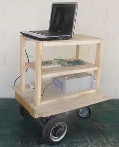
Later I spent time with the Arduino board to control robot bases built out of robotic vacuum cleaners, the cheapest way to get the parts required. The last time I did anything was working on using the Arduino board as an interface to a laptop on a robot base. I use a wireless keyboard to send commands to the robot.
How polite people are is actually cultural and what is acceptable behaviour can also vary between families.
I was just reading this topic in Steven Pinker's book "The Stuff of Thought" in the chapter on "Games People Play" in the section "Touchy, touchy: The logic of politeness".
We are going off topic but I hear what you are saying. For my work I was luckily to travel all over the world (I'm originally Dutch) I have been for moths in asia places like South Korea, Thailand and Vietnam I've been also on the other side of the world for years I lived n Brazil but I have been also many time in Argentina and Chile.
Coming to your point what is polite depends really on the culture you are 100% right about that. And even when I have travelled so much still I have issues see those different cultures and "accept"( accept is the wrong word... I personaly accept everybody) the way people express themself so maybe (most probably) it is me who is too difficult 🤣
I married with a Brazilian women for almost 10 years now but still we have difficulties due to cultural differences. Very funny how those things are grinded in our "blood" to give it a name. Those cultural things dont go away
Grtz,
Ray
Thats a pretty awesome project....very cool you did that! You seem to be a real programmer what is your bacground? Electrical engineering or your a real hobbyist ( not htat htat makes a huge difference) just for curiosity
Grtz,
Ray
For today I'm done with my project. I started around 10 am this morning it's now almost 24h here. I fixed a major bug. But fixing this bug did not help me coming much closer to my goal allthough I know where my problem lies. And this is "gold" if one knows where the problem lies you know where to look in order to ix it so about that I'm happy. But I'm nowhere close to make the bot drive straight using PID control with a speed reference.
SOme people might say just give a output as PWM to both motors but I noticed if I give e.g. 100 PWM to both motors they run at diifferent peeds so this is why i chose to use PID (maybe the wrong solution any other idea is always welcome). But with the harware I'm using now with this project I think PID is a good solution.
The whole part of controlling it by WiFi ...... I can recommend MegunoLink. It is a straight forward program which allows you to make a GUI in the ssame manner as VB6.0. and by coding the right commands it works pretty much straight forward. If I can understnd it you will be able to for sure.
Its just a program one has to pay for if you want to use it for more than 30 days or so.....
Grtz,
Ray
... what is your background?
Just a self taught hobbyist in basic electronics and basic programming.
I see MegunoLink is a commercial product although it has a free trial. I was working on my own version which would have the advantage of not costing anything.
I see ultrasone sensor is Dutch for ultrasonic sensor.
As I am interested in robots so I am interested in your project.
I just installed ArduPID and it all compiled ok so I can play with it now.
I have the hardware you listed as being in your project.
I see MegunoLink is a commercial product although it has a free trial. I was working on my own version which would have the advantage of not costing anything.
I thought of making that but it would take me ages before this would work and as you can see MegunoLink works easy and has a nice self explanatory GUI. Which you can also use later for other projects. I bought as I thought it worth it to have and get lifetime free updates.
I see ultrasone sensor is Dutch for ultrasonic sensor.
Oops sorry about that my English is not the best even I travelled so much never have been good in laguages.. I hd to learn Portuguese years ago it was a hassle. I see I made a lot of errors that post it was late I'll try to pay some attention to it next time.
As I am interested in robots so I am interested in your project.
I think there is an area which is all about project so I could make a thread there maybe it will be fun for others to read and get ideas from as well.
I just installed ArduPID and it all compiled ok so I can play with it now.
Cool, if you use it together with MegunoLink and use the library "Preferences.h" in your code you can send values to the EEPROM inside your ESP. This gives the advantage that you can tune your PID wireless and store the values NVS so nexxt time you start your bot you don't need to send the PID values and during tunning you don't need to upload everytime new PID values.
GRTZ
Ray
Grtz,
Ray
Hi @electricray1981,
I have never built a robot, so I have neither the hardware or direct experience of code to deal with it at that level. However, many years ago, I did build a PID based temperature controller. Now I am not sure if it was good or bad fortune, but this was before microprocessors were available, so the PID was built with analogue electronics, which meant no software to debug, and 'fine tuning' involved twiddling a few potentiometers, having designed the circuit to get me in the 'right region'.
So glancing through the thread, one point struck me, albeit one that might be an artifact of me reading too much into the general conversation drift.
Please accept my apologies if I appear to be trying to teach you what you already know .. as I can't have a face-to-face chat I don't know what level of knowledge and experience to aim at, hence I tend to aim 'low' and ask for your patience.
-------
In the text, you mention that the motors are running at different speed, and looking at the graph in your message that started "And to come back to the subject......", it MAYBE looks like the left and right motors are running at completely different speeds. I emphasise MAYBE, because on my cheap PC, the key colours for Right Speed and Right Output look the same, but I can only see one trace of a similar colour, so I am not sure what I am looking at.
Now earlier in the text, you say you started with just the P-proportional part of the PID adjusting the power drive to your motors, (ie I Integration and D Derivature were inactive), which is a starting point I concur with. However, you say that you could find a position where it oscillated, which is to be expected, and then you backed it off, but you didn't seem to get a position where the motors were the same, or at least very close, to the same speed. That concerns me.
I'll define my own terms "match" and "matching condition" to imply that the measured value (of motor speed in your case) is equal to the set point reference it is aiming for.
@rcc1, correctly says "With a process control loop if you use just the proportional part of the PID you will never get setpoint and measurement to agree." and so on, implying that proportional on its own will struggle to get to a 'perfect match' position.
However, that should be seen in context. Just having proportional control means that if the proportional control is set to 'low gain, it will very 'cautiously' approach the 'matching condition', so that it takes a long time to get close to 'matching condition', whilst ' if the proportional gain is set to 'high gain' and it will overshoot.
It follows that if the gain is set 'very high', the overshoot will be sufficiently prominent to sustain oscillation, whilst if it is backed off to 'high', then some cycles of oscilation may be seen initially, but each successive cycle will decrease in magnitude and it will eventually 'settle down' to a constant level.
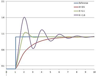
The three cases of 'low', 'medium' and 'high' gain (but not 'very high' gain leading to oscillation) are illustrated in this graph from Wikipedia. https://en.wikipedia.org/wiki/PID_controller
Figure caption - Response of PV to step change of SP vs time, for three values of Kp (Ki and Kd held constant)
This illustrates, it should be possible to adjust the P proportional control to make a pretty fair attempt to reach the 'matching condition', albeit taking more time to reach that condition than if the I and D components are brought into play.
Hence, my concern is that you have not got the P proportional part working correctly, (before getting tangled with the I and D parts). This might be due to choosing inappropriate gain value, but my 'gut' feeling is that the problem is more fundamental. My advice is to revisit the "Proportional only" control regime, as I think you should be able to get the two motor speeds 'very close' to matching when the load and demanded speed are constant. The I and D components should mainly be used to 'speed up' the response to changes of load and demanded speed.
It might be a software bug, but don't discount the possibility of a hardware fault ... more 'intractable' problems often turn out to be things like wiring faults, electrical noise corrupting sensor feedback, and so on. Even something like a failing motor bearing or a sensor slipping could result in varying load or feedback data, leaving the proportional controller continually trying to 'catch up' with the new conditions.
---------
As a last minute thought, I didn't follow the detail, but beware of using 'fancy' smoothing algorithms and libraries to smooth the incoming data from the sensors. Whilst, I am sure in the right circumstances, they can do all sorts of magic, my limited experience from others is that they can also invent their own data, which bears little resemblance to reality, particularly if they have been designed for a specific data corruption problem.
Personally I would start with either no smoothing, or a really simple hand-coded averaging algorithm .. to kick off, maybe something like:
X_n_average = (0.5 * X_n) + (0.3 * X_n-1) + (0.2 * X_n-2)
where X_n is the most recent sensor reading, X_n-1, is the previous one, and so on.
I have absolutely no idea if this will work with your data, so I leave you to investigate and improve on.
Of course, that does not stop you trying the fancier algorithms when you have a more stable base in the future.
------
I think that is probably as far as I can go ... except to hope this is informative and wish you good luck.
Best wishes, Dave
Hi Dave, thank you very much for joining the conversation ang give sote tips this is really helpfull.
In the text, you mention that the motors are running at different speed, and looking at the graph in your message that started "And to come back to the subject......", it MAYBE looks like the left and right motors are running at completely different speeds
The reason you did not see the right motor is because I started to work with the left motor first and see if it would reach the Setpoint (green line). I understand your difficulty to see this and I probably have choses more distinctive colors to emphasize that....my apoplogies for that.
Today Ihad time to carry out more tests and I beleive there is indeed still a fundamental problem which has to do with the feedback signal. I started with a moving avergae which did not work than I went to an exponential filter and this went a bit better but only at High speeds and bigger step responses. I think I understand why and this has to do with the algorithm. So I have to take a step back and try to fix this.
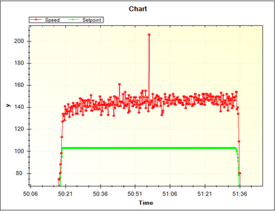
When I started with the project I measured the raw data so no filtering at all. I could find a screenshot of this and maybe you understand why I chose to filter my data.
The red line is the speed in RPM units, the green line was the PWM output value (approx (50% heare) and here is no PID applies. I used this just to check if the measured value by the software is the same as the pulse I could measure with my scope on the speedsensors.
This measured value looks like the grass in my garden and I think if I would send this to the PID control loop it won't do much good.
Personally I would start with either no smoothing, or a really simple hand-coded averaging algorithm .. to kick off, maybe something like:
X_n_average = (0.5 * X_n) + (0.3 * X_n-1) + (0.2 * X_n-2)
I will have a try to do this, I was thinking before reading your post to have a look on a LPF library so the high spikes would be attenuated.
Now I have a question on how to apply your algorithm. Do I have to place this in a circular buffer so I get a kind of FIFO array and previous values will be thrown away?
thanks in advance
Grtz,
Ray
Additionally here a plot which I gues you would like to see:
Red line = Right Motor
Blue line = Left Motor
Green Line = Speed Setpoint
This plot give only the PID with P set so I and D don't have any effect. The filter is still enable (I got some problems turning it of and wanted to show you how it wirks with two motors).
Conclusion here is that both motors will eventually run at the same speed. But as you probably can imagine during ramp up the bot will run the left because the right mtor is running faster as the left during ramp up.
I don't think this is because of the filter I apply (but I agree this needs to be improved). Eventually the both motors should be ramping up equally I guess, and I think this will be a hard task....pffff what am I getting into LOL.
Grtz,
Ray

