It was more about understanding the algorithms hidden in the libraries.
Perhaps assembler is a bit low level although it used to be my language of choice before the Windows OS came along.
Arduino c++ uses functions such as pinMode() digitalRead() attachInterrupt() and so on to make programming the microprocessor much easier so you don't have to understand how it works at the hardware level.
Hi @robotbuilder,
It was more about understanding the algorithms hidden in the libraries.
Thanks for clarifying ... I tried to give my understanding of how the terms originated, which may have detracted from describing the need to look at the algorithms.
I totally agree with your comment, and hence I suggested implementing PID as explicit code.
Best wishes, Dave
Maybe it is very late to react here so I don't know is anybody is really interested in reading it. But many folk have helped me here a lot with trying to get things working as I wanted. It was a big struggle and I have been a bit quite last weeks but that was for one part due to work but also I need to dive into the matter to get this working, and I'm pretty happy that I got to a point that this motor control I got under "control".
I have a bit different hardware setup now. a different motor driver board and different encoders (which came with the motors). But besides of that I read a lot about PID tuning and dived a bit more into how these PID libs working.
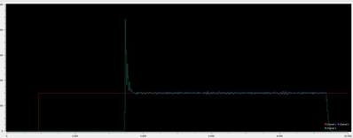
One of the big issues I had was that I never even came close to the speed setpoint I gave to the controller. I I seem to have managed it. I will show here a picture and try to explain what it show.
The red line is the desired setpoint we see it here go up from zero to the desired value at the moment I have connection But there is not yet power supply to the motor driver board. At the moment I turn on the power supply we see the green and magenta line go up. The green and magenta lines are the speed measurements. So these values need to end up on the red line which is the setpoint.
This seems to work there is indeed a big overshoot and I think I know how to reduce this but that is for later work (I will explain). I'm verry happy that the control circuit reaches its setpoint. This is done with a PID controller and a Arduino NANO 33 IoT. In fact it is only a PI controller and tuning without the Ki I get a huge difference between setpoint and measured value tuning the I makes me come to this result.
This huge overshoot I could reduce more by working with the Kd gain but I have waited with that for now cause these tests were done unloaded. I mean by that that the wheels don't feel any inertia from the wight of the bot. I will tune it more. I just wanted to share that I was eventually able to make a PID control working with a Arduino and encoders. There is a bit more to tune I know.
Now how I appriached this is that I count in a interval of 100ms the amount of pulses the enconder counts (with interrupts) with this value I comput the rpm value. This value I use for the PID regulation, but the PID regulation has also a time to do its calculations. And this is a important thing to take into acount.
The library I used has a setting where you can set it's sample time and it basicallly meanse how many times per second it computes it's algorithm and send new outputs. This MUST match with the speed you sample the speed. And this was a bit of tuning.
Maybe for many people this is a easy thing to tackle for me it took a while and learned a lot of things Again the overshoot I can reduce I think and maybe it is not even to much of an issue when seeing the bot driving I will see
Grtz,
Ray

