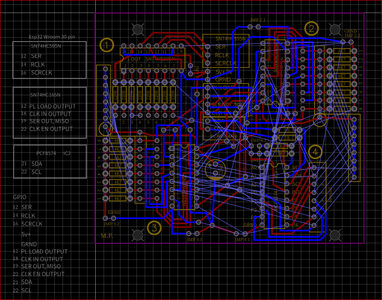
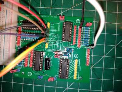
Added the script at an ESP32 Wroom 32 pin from the shiftregisters artichle here at the webpage.
Got a print board fabricated and added the wires to it. It works, but will only show the results,
when the LSBFIRST is exchanged with MSBFIRST. This is okay, while when testing the 8 inputs, only 7 of those will show a result and/or a difference. The D0 at ic pin 11, is not showing any difference than 11111111, which is the result when no button is hit.
Tried exchange the IC, and its the same. What to do?
/*
  74HC165 Shift Register Demonstration 1
  74hc165-demo.ino
  Read from 8 switches and display values on serial monitor

  DroneBot Workshop 2020
   https://dronebotworkshop.com
*/

// Define Connections to 74HC165

// PL pin 1
int load = 13;
// CE pin 15
int clockEnablePin = 22;
// Q7 pin 7
int dataIn = 19;
// CP pin 2
int clockIn = 18;

void setup()
{

  // Setup Serial Monitor
  Serial.begin(115200);

  // Setup 74HC165 connections
  pinMode(load, OUTPUT);
  pinMode(clockEnablePin, OUTPUT);
  pinMode(clockIn, OUTPUT);
  pinMode(dataIn, INPUT);
}

void loop()
{

  // Write pulse to load pin
  digitalWrite(load, LOW);
  delayMicroseconds(5);
  digitalWrite(load, HIGH);
  delayMicroseconds(5);

  // Get data from 74HC165
  digitalWrite(clockIn, HIGH);
  digitalWrite(clockEnablePin, LOW);
  byte incoming = shiftIn(dataIn, clockIn, MSBFIRST);
  digitalWrite(clockEnablePin, HIGH);

  // Print to serial monitor
  Serial.print("Pin States:\r\n");
  Serial.println(incoming, BIN);
  delay(200);
}
regards
Fungreenfox
Added the script at an ESP32 Wroom 32 pin from the shift registers article here at the webpage.
Where is the webpage?
Added the script at an ESP32 Wroom 32 pin from the shift registers article here at the webpage.
Where is the webpage?
Here. https://dronebotworkshop.com/shift-registers/
regards
Fungreenfox
My first thought is the code was written for an Arduino Uno so maybe will not work with the esp32 ?
I noticed this in code online for using a shift register for writing to LEDS using the different boards.
// for Arduino Microcontrollers
int latchPin_SIPO = 5;
int clockPin_SIPO = 7;
int dataPin_SIPO = 6;
// for ESP8266 Microcontrollers
//int latchPin_SIPO = D2;
//int clockPin_SIPO = D0;
//int dataPin_SIPO = D1;
// for ESP32 Microcontrollers
//int latchPin_SIPO = 21;
//int clockPin_SIPO = 23;
//int dataPin_SIPO = 22;
I suggest looking for code specifically for reading button input using the ESP32
Although I have an esp32 I haven't actually used it yet.
pin 19 or 21 will work for Q7, no change. the D0 pin is always typen out continously, and its unclear what we get at the fixed gpio at the ic, because that value is repeated when nothing is hit.
regards
Fungreenfox
I don't have time myself to study the code examples but if you are using the esp32 then this has code and wiring for using the esp32 to input and output using a shift register.
https://diyi0t.com/shift-register-tutorial-for-arduino-and-esp8266/
Hi @fungreenfox,
Odd behaviour indeed. As someone who always triple checks everything, may I suggest...
Have you checked the voltage on chip pin D0 pin 11, with switch pressed and not pressed, to make sure the correct voltages are being fed to the chip?
Note, it is essential to put your meter probe actually onto the chip pin itself. Sometimes the breadboards, etc, fail to make good connections, which can give confusing behaviour.
[ Also, check the switch for D1, chip pin 12, is changing the correct bit on the display. When printing out multiple bits like this, sometimes people make a software mistake and print the bits in reverse order, although I think this is unlikely in this case. ]
Just a thought to eliminate a couple of possible problems. Best wishes, Dave
Adding the gerber for the print board, if anyone can discover some that should be different.
https://www.dropbox.com/s/amh5h6q731j78sl/Radio%20etage%20shiftregister%20complimentary.zip?dl=0
regards
Fungreenfox
@davee Thanks for the comment. The project was moved to a print board as shown here.
The pins have been messured, and they equally show same result. Each pin will give a different number to work with, except the D0, that runs odd continuosly. It seems to be the code.
regards
Fungreenfox
Hi @fungreenfox,
Sorry, I only glanced at your photo, but it isn't easy to track every connection without spending a lot of time on it, which I am not keen to do now.
My 'gut' feeling is that you have a wiring issue, but no direct proof to support that hypothesis.
--------
Wiring issues are not always simple wrong pins,etc. ... sometimes they include connections that do not behave as first expected. Remember even these 'humble' HC series chips are capable of very high speed switching and transient currents when they change state can be measured in Amps. A few millimetres of wire or copper track is far from a perfect conductor under these conditions, but rather resistor(s), capacitor(s) and inductor(s) all rolled together.
I have just noticed that your board only appears to have one capacitor, and that is electrolytic, which is a useful start, but not the whole story. Furthermore, I think your tracking 'mixes' the power with 'data/control' pins, so that any transients caused by the chip demanding current when changing state might be 'seen' by a 'data/control' pin, so that they see a different voltage from that expected -- commonly known as a glitch which is likely to need a fast oscilloscope, careful probing and luck to find.
However, before trying to prove such a hypothesis, a simple precautionary change might help ....
I would expect to see a ceramic across the power pins (Vcc to Gnd) of each digital chip ... value not critical, say 0.1 microFarad. (Purists might recommend two different values, e.g 0.001uF and 0.1uF in parallel for optimal decoupling, but start simple.) These capacitors should be connected with wires as short as possible, directly to the chip pins (or their socket pins if the chips are socketed).
------------
And if extra capacitors haven't helped, a software concern ... your listing includes
byte incoming = shiftIn(dataIn, clockIn, MSBFIRST);
which is a bit of black box routine, although I would expect it to work .... but you never know ...
I think I would recommend adopting a low level 'one step at a time' approach .. maybe playing with the code using your own software steps to clock data from one pin to the next and watch it emerge using a voltmeter ...
-----------
Sorry, it is tricky to diagnose over a forum. However, with luck that photo may have helped.
Best wishes, Dave
Setting it up on bread board with only one 74hc165, will act the same way. A ceramic over the pwr pins, is worth trying. Are those the small dark orange ones saying 104?
regards
Fungreenfox
hi @fungreenfox,
Are you saying that you have set up a '165 on the breadboard and it is still reacting in the same way?
I have fairly recently acquired a small plastic bag of 'orange circles' with 104 printed on them, which purport to be 0.1uF ... so a qualified Yes to your answer ... bearing in mind I haven't actually tried or tested one yet.
In past years, when most of my component buying was associated with work, I would have used parts from more 'established' brands, hence my caution. 😀
Good luck, Dave
@fungreenfox fyi @davee Just a shot in the dark here gents, is it ok to NOT specify a pinmode of INPUT_PULLUP? Without that I think on an esp32 the input is undefined. I am surprised Bill didn't use it on the arduino UNO as it definitely is undefined. I am probably wrong, but can't hurt to try.
First computer 1959. Retired from my own computer company 2004.
Hardware - Expert in 1401, and 360, fairly knowledge in PC plus numerous MPU's and MCU's
Major Languages - Machine language, 360 Macro Assembler, Intel Assembler, PL/I and PL1, Pascal, Basic, C plus numerous job control and scripting languages.
Sure you can learn to be a programmer, it will take the same amount of time for me to learn to be a Doctor.
Hi Ron @zander,
I am not certain which pin ... or which code sketch you are referring to.
74HC165 Shift Register Demonstration 1
contains
// Q7 pin 7int dataIn = 5;and
pinMode(dataIn, INPUT);
As Q7 output on the 75HC165 is CMOS output, which drives both high and low, it does not need the "pullup" part of an "INPUT_PULLUP" pin definition - a simple "INPUT" definition is sufficient.
------
Assuming the ESP32 version of the compiler supports both INPUT and INPUT_PULLUP, I would expect it to behave in the same way as the 'original' Arduino devices.
The "PULLUP" part enables a high value resistor, internal to the microcontroller, connected between the pin and Vcc. It is designed for applications like an external switch or jumper, connected between the pin and ground, saving the need for a resistor.)
Best wishes, Dave
@davee I was referring to the pinmode statement that has INPUT.
pinMode(dataIn, INPUT);
Without the _PULLUP added the state can be undecided as it says here
This also means however, that pins configured as pinMode(pin, INPUT) with nothing connected to them, or with wires connected to them that are not connected to other circuits, will report seemingly random changes in pin state, picking up electrical noise from the environment, or capacitively coupling the state of a nearby pin.
Since I don't know how the physical circuit connections are I proposed it as I said as a 'shot in the dark'
It is simple to test, but carry on, it's fun to watch.
First computer 1959. Retired from my own computer company 2004.
Hardware - Expert in 1401, and 360, fairly knowledge in PC plus numerous MPU's and MCU's
Major Languages - Machine language, 360 Macro Assembler, Intel Assembler, PL/I and PL1, Pascal, Basic, C plus numerous job control and scripting languages.
Sure you can learn to be a programmer, it will take the same amount of time for me to learn to be a Doctor.


