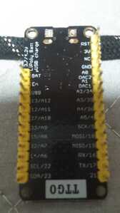
I have an original ESP32 board that is either a Lilygo or a clone. The serial port (USB) is no longer functional. Nothing happens when I plug it in to a USB port. I have other boards that work fine, so I know the computer port and cable are working. I'm guessing static might have gotten to the converter. I've attached a photo of the bottom of the board with the pinout and I see it has both an RST and EN pin. Googling both I have conflicting information. In one case someone said they were identical, in another it said RST was pin 9. Anyway I don't much care unless one of them is the programming pin. I have a FTDI cable that I'm wanting to hook up to bypass the failing com port but I don't see that IO0 (zero) is brought out. I did find this statement:
"There are five strapping pins: GPIO0, GPIO2, GPIO5, GPIO12, and GPIO15. These pins are used to put the ESP32 into BOOT mode (to run the program stored in the flash memory) or FLASH mode (to upload the program to the flash memory). Depending on the state of these pins, the ESP32 will enter BOOT mode or FLASH mode at power on."
But it didn't say what the polarity of the pins should be for what mode. I know on the 8266 that bringing pin 0 to ground and pressing the reset button and then releasing pin 0 puts it into flash mode so it will accept a program download. I'm guessing the ESP32 does the same. Does that mean that I could use pin 2, 5, 12, or 15 in the same manner? If I could get it to load a sketch one time that has OTA, I could then not need the programming cable.
Thanks,
Jim.
@k4gvo The first thing I would do is check Bills latest video/article and use the website that analyzes the board. The next step is to determine what chip is on the board to connect the USB (there are two different chips with different drivers). I have dozens of esp32 boards and NONE of them do anything when I plug them in. I also have never done (although I know it needs it rarely) that push this button followed 1.3us later by push that button now plug in your cable stuff.
Here is link to the tool HERE
And this link has even more (see Bills article at HERE )
Just connect the board with a data+power USB cable, open the Blink sketch, go into either the new style or old Style (Tools menu) to select the closest board (I use DOIT) and select the USB serial port. If the LED blinks after uploading (no buttons or jumpers needed) then the board is fine.
If the board test link Bill posted passed the board and the Blink sketch fails, the board is most likely garbage.
As to the different pins you mentioned, there is a video/article that covers all that, but that is not likely the source of your problems, if needed I will dig up that link later.
First computer 1959. Retired from my own computer company 2004.
Hardware - Expert in 1401, and 360, fairly knowledge in PC plus numerous MPU's and MCU's
Major Languages - Machine language, 360 Macro Assembler, Intel Assembler, PL/I and PL1, Pascal, Basic, C plus numerous job control and scripting languages.
Sure you can learn to be a programmer, it will take the same amount of time for me to learn to be a Doctor.
@k4gvo I just remembered a few other resources. As always, consult the randomnerds at HERE . For the nitty gritty details, consult this HERE under Boot Mode Selection, and the master datasheet is enclosed as attachment. The section you want is likely 2.4 Strapping pins.
First computer 1959. Retired from my own computer company 2004.
Hardware - Expert in 1401, and 360, fairly knowledge in PC plus numerous MPU's and MCU's
Major Languages - Machine language, 360 Macro Assembler, Intel Assembler, PL/I and PL1, Pascal, Basic, C plus numerous job control and scripting languages.
Sure you can learn to be a programmer, it will take the same amount of time for me to learn to be a Doctor.
The fact it used to work means something has changed. I'm running Linux and when I plug the cable into the computer and tail dmesg I see nothing that would indicate a device has been recognized by the OS. Since it isn't recognized i don't have a com port to connect a program to. Normally when you connect a board to the USB on Linux dmesg reports that it finds a port and often it is /dev/ttyUSB0. If it doesn't then there is no way that I can do what you suggest.
I read your references but they didn't really address the question can I use the alternate pins the same way I can use GPIO0 since GPIO0 isn't broken out AFAIK.
Thanks,
Jim
@k4gvo GPIO0 is almost always connected to the BOOT button. I just plugged in a known good esp32 and nothing shows in dmesg.
Are you sure you have the right USB driver? I thin there are two different chips that an esp32 might use.
First computer 1959. Retired from my own computer company 2004.
Hardware - Expert in 1401, and 360, fairly knowledge in PC plus numerous MPU's and MCU's
Major Languages - Machine language, 360 Macro Assembler, Intel Assembler, PL/I and PL1, Pascal, Basic, C plus numerous job control and scripting languages.
Sure you can learn to be a programmer, it will take the same amount of time for me to learn to be a Doctor.
Hi @k4gvo,
I recently had a 'nuisance' board .. in that case I could program the board, but only with some well-timed use of the two buttons during the download process. I managed to find the fault, once I figured out what the circuit was.
Although you probably have a different fault, the diagnosis method is probably similar. Whether it is worth the time, given similar boards are probably only a very few dollars, only you can judge ... I fixed mine as a personal challenge ... definitely, not as an economic repair.
---------
The short answer, is look/determine the circuit of your board ... there are a lot of schematics on the web, but it can still be tricky.
Note, if the USB chip has died, it might play 'nasty' and present a short on its output pins, making a direct connection impossible without removing the chip.
------------------ IF you still want to proceed ...
I started by looking for the USB chip. It is often a square, surface mount board with about 7 leads on each side, and it will probably be fairly near the USB socket. Try looking for the chip and see if you can find a part number, like CHxxx or CHxxxx where each x is a number (0..9), hoping the supplier has not removed all markings ...
If you can find it, then that will be a reasonable clue as to what the board circuit will be.
I then used Google, plus 'buzzing' the board out, and found the board I had was fairly similar to a circuit Espressif had published ... except for some changes, probably to get round chip supply problems, or to use up an old batch of cheap chips.
In my case, the USB chip was different from all circuits I could find .... so I started with the data sheet for the chip that had been fitted.
-------
If you can find the chip type, but can't find the circuit, try here with chip type and the best photo you can make of the component side of the board. No promises, but someone might recognise it.
Good luck, Dave
@davee @k4gvo I think the esp32 uses one of two usb to serial chips, the SiLabs CP2102 and WCH CH340. I forget which is which, but one requires pressing the boot button to do an upload, the other does not. Maybe tomorrow I will see if I have both and do a quick test.
First computer 1959. Retired from my own computer company 2004.
Hardware - Expert in 1401, and 360, fairly knowledge in PC plus numerous MPU's and MCU's
Major Languages - Machine language, 360 Macro Assembler, Intel Assembler, PL/I and PL1, Pascal, Basic, C plus numerous job control and scripting languages.
Sure you can learn to be a programmer, it will take the same amount of time for me to learn to be a Doctor.
I'm pretty sure the USB chip is bad. This board does not have a program button, only a reset button. It was working just fine until it wasn't. I run Linux and pretty much all of the ordinary USB chip drivers are present. I've been programming MCUs for nearly 10 years and have yet to find a board that the OS didn't see. I'm not going to replace the USB chip, I don't have the ability to solder or desolder chips that small, so what I want to do is connect my FTDI cable to the RX and TX ports and figure out which pin, other than GPIO0 can be used to put the board in upload mode. If it doesn't work, I'll toss it but if I can get it programmed once then I can use OTA software to program it in the future. It's just an exercise since I have a few other ESP32 boards that I can use. I am currently in an RV away from home and don't have the ability to view the tiny print on a tiny chip. My eyes are not as good as they once were. But it's a moot point in any case since I'm not going to replace it.
@zander This board has alway presented itself as connected to /dev/ttyUSB?. If it didn't then the programming software wouldn't be able to connect to it. If you are saying you didn't see it in dmesg, then do you have /dev/ttyUSB0 or similar? I can only say that your dmesg log isn't configured like mine is if you see the device. If I don't see it in dmesg, then there isn't a /dev/ttyUSB? device. I'm running Linux Mint 20 which is derived from Ubuntu and Debian.
Thanks for the suggestions.
Jim
Here's the output from plugging in an ESP8266 followed by plugging in an ESP32.
 dmesg | tail
[ 7967.854962] usb 2-1.2: new full-speed USB device number 5 using ehci-pci
[ 7967.963874] usb 2-1.2: New USB device found, idVendor=1a86, idProduct=7523, bcdDevice= 2.54
[ 7967.963877] usb 2-1.2: New USB device strings: Mfr=0, Product=2, SerialNumber=0
[ 7967.963879] usb 2-1.2: Product: USB2.0-Ser!
[ 7968.004770] usbcore: registered new interface driver usbserial_generic
[ 7968.005347] usbserial: USB Serial support registered for generic
[ 7968.014908] usbcore: registered new interface driver ch341
[ 7968.015348] usbserial: USB Serial support registered for ch341-uart
[ 7968.019351] ch341 2-1.2:1.0: ch341-uart converter detected
[ 7968.023953] usb 2-1.2: ch341-uart converter now attached to ttyUSB0
E6520:~$ dmesg | tail # Above was a D1 Mini
[ 8025.975464] usb 2-1.2: new full-speed USB device number 7 using ehci-pci
[ 8026.115138] usb 2-1.2: New USB device found, idVendor=10c4, idProduct=ea60, bcdDevice= 1.00
[ 8026.115141] usb 2-1.2: New USB device strings: Mfr=1, Product=2, SerialNumber=3
[ 8026.115143] usb 2-1.2: Product: CP2102 USB to UART Bridge Controller
[ 8026.115145] usb 2-1.2: Manufacturer: Silicon Labs
[ 8026.115146] usb 2-1.2: SerialNumber: 0001
[ 8026.156985] usbcore: registered new interface driver cp210x
[ 8026.157127] usbserial: USB Serial support registered for cp210x
[ 8026.157245] cp210x 2-1.2:1.0: cp210x converter detected
[ 8026.161486] usb 2-1.2: cp210x converter now attached to ttyUSB0

# above was a generic ESP32 wroom ESP32D (I think)
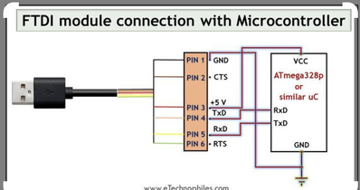
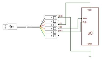
@k4gvo Strange I don't see my board when I do a dmesg. Your idea of connecting an ftdi cable and loading the OTA code sounds like it will work. I do have boards with no boot/flash button, and they work just fine with no diddling with the board, just connect them and press upload on the IDE. My assumption has always been that there is some sort of protocol in the USB interface that does away with the need to press a button or manipulate GPIO0. Looking at the FTDI pinout I would make a wild guess it's RTS followed by CTS.
Here is a wiring diagram that shows only +5, G, TX, and RX. Try that first maybe.
Here is a more generic diagram
First computer 1959. Retired from my own computer company 2004.
Hardware - Expert in 1401, and 360, fairly knowledge in PC plus numerous MPU's and MCU's
Major Languages - Machine language, 360 Macro Assembler, Intel Assembler, PL/I and PL1, Pascal, Basic, C plus numerous job control and scripting languages.
Sure you can learn to be a programmer, it will take the same amount of time for me to learn to be a Doctor.
Nogo, I can't get it to do anything. I give up. Thanks to all.
Jim
@k4gvo Thats ok, most of us have destroyed a board or two along the way. One of the diagrams shows 5V but hopefully you know the esp32 is a 3.3v board, only the USB connector can be 5v. That mistake will kill a board.
First computer 1959. Retired from my own computer company 2004.
Hardware - Expert in 1401, and 360, fairly knowledge in PC plus numerous MPU's and MCU's
Major Languages - Machine language, 360 Macro Assembler, Intel Assembler, PL/I and PL1, Pascal, Basic, C plus numerous job control and scripting languages.
Sure you can learn to be a programmer, it will take the same amount of time for me to learn to be a Doctor.
@k4gvo Thats ok, most of us have destroyed a board or two along the way. One of the diagrams shows 5V but hopefully you know the esp32 is a 3.3v board, only the USB connector can be 5v. That mistake will kill a board.
The only way I've used this board was via the USB connector. It is being used as a dev board without any peripherals. The software will eventually be on a ESP32 dual relay board, but that board is painful to use since it doesn't have a USB connector and to program it I have to manipulate the reset and boot buttons that only work some of the time. While developing the software I don't really need to toggle relays. The application is a watchdog for a remote installation.l I'll be monitoring a system to make sure it is up and running. Likewise with the router and modem. If any of the devices seem to be non operational, I'll power cycle them. The site is located about 8 hours from home so it's extremely difficult to just dash over to reset a device.
Thanks,
Jim
@k4gvo Will OTA help?
First computer 1959. Retired from my own computer company 2004.
Hardware - Expert in 1401, and 360, fairly knowledge in PC plus numerous MPU's and MCU's
Major Languages - Machine language, 360 Macro Assembler, Intel Assembler, PL/I and PL1, Pascal, Basic, C plus numerous job control and scripting languages.
Sure you can learn to be a programmer, it will take the same amount of time for me to learn to be a Doctor.


