Hello,
I need help to find fault in my perfboard. I have used Dronebot scematic for servo tester
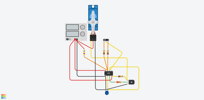
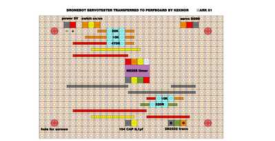
: Then I have used Tinkercad, adjusted som resistores and have a god result for the speed and the angle of the servo. Then I have made a plan in Sketchup for the layout on a perfboard. Then I have solderes all the components on the perfboard and by applying power (5v) nothing happens..... I have tried to find faults in the schematic and in the perfboard itself but have not found the error. Can anyone help? See the following pictures. ( ps I am a beginner in electronics with some experience)
Any suggestions will be greatly appreciated.
I can see a lot of suspicious solder joints and a few that are for sure bad. I think your soldering iron needs to be hotter, and try using either a liquid flux or paste and go over all the solder points again to make them perfect. A good starting point is 650F, then if results warrant +50 for lead free and -50F for lead. I also prefer the thinner solder wire as it melts faster and has a higher flux to solder ratio, but don't go to small. All my gear is in transit so I can't measure my solder.
If you are seeing too much solder buildup, use a desoldering wick. Pick a size that matches the trace size on the PCB plus a large size or even a special 'mat' for large areas of cleanup.
First computer 1959. Retired from my own computer company 2004.
Hardware - Expert in 1401, and 360, fairly knowledge in PC plus numerous MPU's and MCU's
Major Languages - Machine language, 360 Macro Assembler, Intel Assembler, PL/I and PL1, Pascal, Basic, C plus numerous job control and scripting languages.
Sure you can learn to be a programmer, it will take the same amount of time for me to learn to be a Doctor.
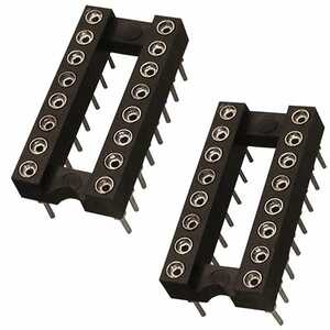
Hi @keknor, yes, I have to agree with @Ron about the soldering..also, it is probably not a good practice to solder the pins of IC chips directly, but use IC extenders like these:
to keep from damaging your 555 IC.. they come in a variety of sizes from 8 pin dual in-line (DIL)40 pin, the ones shown in the photo are 16 pin. Soldering is some what of an art, and takes a lot of practice to learn to do it correctly and efficiently. Don't get discouraged as everyone goes though this phase of getting it wrong, then learn how to do it right.
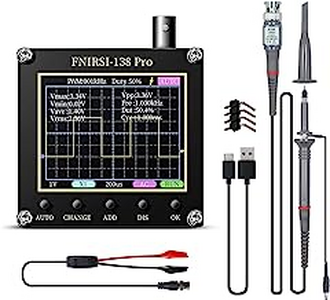
Probably will be helpful to also invest in a cheap oscilloscope like this one:
there are many on Amazon.com , or where ever you buy electronic test equipment from for as low as $30 US... This will enable you to see if your 555 timer is indeed putting out the correct pulse frequency and amplitude for what you are trying to do.
Good luck,
regards,
LouisR
LouisR
@inst-tech @keknor I totally agree with Louis.
First computer 1959. Retired from my own computer company 2004.
Hardware - Expert in 1401, and 360, fairly knowledge in PC plus numerous MPU's and MCU's
Major Languages - Machine language, 360 Macro Assembler, Intel Assembler, PL/I and PL1, Pascal, Basic, C plus numerous job control and scripting languages.
Sure you can learn to be a programmer, it will take the same amount of time for me to learn to be a Doctor.
Thank you all for god and quick replies.
About the soldering on the perfboard. It may not look so neat. its my firsi try on a perfboard, but I have soldered models for many years. Here I used 400C temp. and liquid flux. I use a TS100 soldering iron with a wedged tip. I have a pin point tip also. Ill change to that one from now on. I did bend the component wires on the solderside before soldering. Is it better practice to keep them straight through the holes?
Oscilloscope. Yes I bought an DSO from China som years ago but I could not get it to function properly. Bad quality?
I have a good Sinometer 830B. With this I have measured 5V across Ne555 pin 8 to 1 and pin 4 to 1
I also measured Ohm across the copper strips where I have soldered components.Seems to be ok after I scraped a couple suspicious isolating groves in the Perfboard.
I suspect that I have done something wrong with the placement/arrangement of the wiring /components on the perfboard but can`t figure it out. Any ideas here?
@keknor Your temperature is much too low. It should be 650.
Something else you can do is to use your VOM to trace the 5V line with power ON. You can do similar with the G lines but with power OFF.
Beyond that, use the VOM in continuity mode to trace all the 555 connections all the way to a logical end. If that does not turn up a mis-wire then maybe the 555 chip is fried or you have a really bad connection somewhere.
Good luck!
First computer 1959. Retired from my own computer company 2004.
Hardware - Expert in 1401, and 360, fairly knowledge in PC plus numerous MPU's and MCU's
Major Languages - Machine language, 360 Macro Assembler, Intel Assembler, PL/I and PL1, Pascal, Basic, C plus numerous job control and scripting languages.
Sure you can learn to be a programmer, it will take the same amount of time for me to learn to be a Doctor.
Thanks again, Ron.
I calculated 670F to be about 377 C, so using 400C is ok. I live in Norway. Its late now . I try your measuring tips tomorrow.
PS I include the schematic from Tinkercad
@keknor My mistake, I didn't notice it was in C. I can't figure out the various diagrams. If I have to translate each depiction of the 555 I am afraid I can't help. If you can redraw maintaining Bill's depiction and in the same orientation as the attached picture maybe I can help.
First computer 1959. Retired from my own computer company 2004.
Hardware - Expert in 1401, and 360, fairly knowledge in PC plus numerous MPU's and MCU's
Major Languages - Machine language, 360 Macro Assembler, Intel Assembler, PL/I and PL1, Pascal, Basic, C plus numerous job control and scripting languages.
Sure you can learn to be a programmer, it will take the same amount of time for me to learn to be a Doctor.
@zander . Hi Ron..I have already checked his drawing and it's correct.. so either he has fried the 555, has a cold solder joint, or mis-wired something. Your suggestion on how to trouble shoot is the was to go. That way he can at least verify the continuity and that he has the connections in the right places..
@keknor.. yes , that's the problem with cheap oscilloscopes , the quality my not be very good, but if it works, your not out a lot of money. You'll need an oscilloscope if your trying to check that the pulse frequency is in the right range that you want for your project.
BTW, with the values of resistors and capacitor your using, your pulse frequency will be around 30 Hz with the 10k resistor switched in, and 29.45hz with the 20K resistor.
Having the scope would allow you to see that the 555's ouput is working..let us know if you need more information or help..
regards,
LouisR
LouisR
@inst-tech A logic analyzer could also be used, and they are under $50.
My money is still on a cold solder joint.
First computer 1959. Retired from my own computer company 2004.
Hardware - Expert in 1401, and 360, fairly knowledge in PC plus numerous MPU's and MCU's
Major Languages - Machine language, 360 Macro Assembler, Intel Assembler, PL/I and PL1, Pascal, Basic, C plus numerous job control and scripting languages.
Sure you can learn to be a programmer, it will take the same amount of time for me to learn to be a Doctor.
@zander , Ron..indeed you can use a logic analyzer, but I like to see the wave form, and duty cycle of the output so I can easily adjust the frequency. It's just a matter of preference.
regards,
LouisR
LouisR
@inst-tech I mentioned it as a second choice for those who don't have an oscilloscope.
First computer 1959. Retired from my own computer company 2004.
Hardware - Expert in 1401, and 360, fairly knowledge in PC plus numerous MPU's and MCU's
Major Languages - Machine language, 360 Macro Assembler, Intel Assembler, PL/I and PL1, Pascal, Basic, C plus numerous job control and scripting languages.
Sure you can learn to be a programmer, it will take the same amount of time for me to learn to be a Doctor.
Thanks again to all of you. Its 7pm here now and I am out for the evening (argentine tango) I will test your advice/suggestions tomorrow
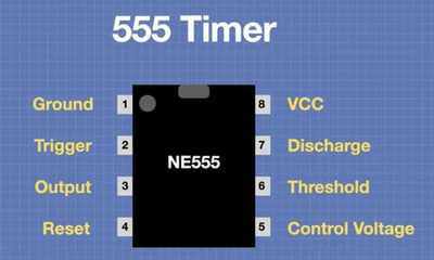
The 555 in my drawing have this orientation
8-7-6-5
1-2-3-4
Hello,
I need help to find fault in my perfboard. I have used Dronebot scematic for servo tester Then I have used Tinkercad, adjusted som resistores and have a god result for the speed and the angle of the servo. Then I have made a plan in Sketchup for the layout on a perfboard. Then I have solderes all the components on the perfboard and by applying power (5v) nothing happens..... I have tried to find faults in the schematic and in the perfboard itself but have not found the error. Can anyone help? See the following pictures. ( ps I am a beginner in electronics with some experience)
Any suggestions will be greatly appreciated.
Everyone looks at a project through glasses of their own experiences. I'm not much of a hardware guy. I have to do from examples or get help from the kind people here. And I understand sometimes doing things is for the fun of making it work the hard way... not necessary the easiest/cheapest/quickest.
Another way of looking at it... you're building your house with screws and I only have a hammer. So, I look for ways of doing it with nails. 😆
It seems to me with a single potentiometer and a Wemos board and some software (nail) you could make a very fine PWM based controller to control the servo. With a little more software, you could get rid of the potentiometer and add the output capabilities of oscilloscope / logic analyzer without adding any hardware... including the oscilloscope / logic analyzer.
3 lines of code = InqPortal = Complete IoT, App, Web Server w/ GUI Admin Client, WiFi Manager, Drag & Drop File Manager, OTA, Performance Metrics, Web Socket Comms, Easy App API, All running on ESP8266...
Even usable on ESP-01S - Quickest Start Guide
Hi @inq,
I totally agree with you that any small 'Arduino-friendly' microcontroller board, ESP8266s included, can do the task, and if creating the desired, and maybe complex, waveforms is the principal aim, then it is hard to beat. Though for a beginner, who doesn't have experience with software development, it also has it has challenges, and if (in the now unlikely event) you don't have spare computer etc, also costs, to get started.
'Pre-computer'/hardware only approaches, such as the redoubtable 555 timer can also do some of these tasks, and to someone who is just starting to look at hardware, figuring out how to solder etc., and so on, simple projects like this one are perhaps the least painful way of starting. Trouble is, when something goes wrong, figuring out the problem without relatively expensive toys like oscilloscopes can also be tricky
So as someone who has lived in the twilight between hardware and software for a long time, I can appreciate both sides to the story. And whilst those (like yourself) who are highly competent in one camp, whilst also have a good intuitive feel for the other camp, will naturally wonder why anyone should go for a 555 timer, when it might need a 'scope to easily figure out why it doesn't work, personally I am pleased to see the guidance Louis (@inst-tech) and Ron (@zander) have offered.
To me, the reason would be a hope of flexibility in the future. If I can buy an interesting module for a few dollars/pounds, then I am likely to go that way. But if it doesn't meet my aims, but a few chips, etc can be soldered together to good effect, then I have a larger range of choices. The present availability of computing 'bricks' from China, sometimes delivered at about the same cost to me of just posting the same items across the country, obviously changes the economics of the situation, but only if the items I want match those marketed.
I confess, with the developments in FPGAs, neural nets, software defined radio and so on, which increasingly use software techniques to achieve aims that were formally in the hardware domain, I may be following the fate of the dinosaurs, but even they managed to hang around for quite a few (million) years. My aspirations are far more modest. 😊
Just a friendly discussion point .. very best wishes to all, Dave

