Thank you for your kind answers, Ill study it!
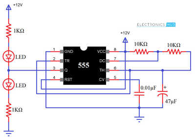
I found this NE555 tester:
https://www.electronicshub.org/how-555-timer-ic-testing-circuit-works/
I made it in Tinkercad:
It blinked green-red-green etc.
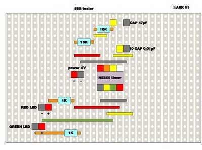
Then i mase a layout in sketchup:
and finaly assembled the components on the perfboard.
Testresults for five new NE555 timers: Green led lights continually.
Either some misunderstanding in the layout or all NE555 faulty?
I do believe the soldering is ok. All components are as described on the internet.
@keknor I doubt any of your 555's arrived damaged. They may be now, though. My recommendation is to forget Tinkercad, forget SketchUp. Build the circuit on a normal breadboard.
First computer 1959. Retired from my own computer company 2004.
Hardware - Expert in 1401, and 360, fairly knowledge in PC plus numerous MPU's and MCU's
Major Languages - Machine language, 360 Macro Assembler, Intel Assembler, PL/I and PL1, Pascal, Basic, C plus numerous job control and scripting languages.
Sure you can learn to be a programmer, it will take the same amount of time for me to learn to be a Doctor.
Is there some reason that you rotate the actual picture and the layout diagram by 90 degrees so we can't line up the assembly directly ?
I think we need to see the soldering on the reverse of the perfboard because your physical and layout diagrams don't appear to match. It's not clear whether this is poor layout skills or misinterpretation of the diagram.
As an example, consider the second capacitor in from the bottom right of the layout. I can't tell what value it is because it's unreadable on the image sent. It's 'top' is clearly labelled yellow but it DOES NOT LINE UP with the yellow pin on the NE555 nor the other capacitor's yellow tag.
I don't mean to be rude, but electronics requires a certain measure of neatness and accuracy. You may need to concentrate on simpler circuits for a while to prepare yourself. Practice may not make perfect but it usually makes better 🙂
Anything seems possible when you don't know what you're talking about.
@keknor , While it's hard to tell it all the connections are good..the layout on the board indicates that all the components are in the right places.. However, it is un-likely that all the 555 timers are bad, and most likely a bad connection some where. the fact that the red led is on continuously indicates that the 555 is not oscillating...again this is when a cheap oscilloscope comes in handy to show you if the capacitor is even charging or not.
If you place you VOM meter positive probe on pin 2 and the negative probe of your meter to your power supply negative terminal( black wire on your perf board, you should see the the voltage rising to about 2/3 of supply voltage, and dropping off to around a 1/3 of less, then repeating @ ~ 1 sec intervals, one led will be on for approx. .65 sec, and the other will be on for about .33 sec. when it's working correctly..carefully check all your connections, as I'm fairly sure you have a bad connection some where.
Hope this helps,
Regards,
LouisR
LouisR
@keknor Glad to see it's working.
First computer 1959. Retired from my own computer company 2004.
Hardware - Expert in 1401, and 360, fairly knowledge in PC plus numerous MPU's and MCU's
Major Languages - Machine language, 360 Macro Assembler, Intel Assembler, PL/I and PL1, Pascal, Basic, C plus numerous job control and scripting languages.
Sure you can learn to be a programmer, it will take the same amount of time for me to learn to be a Doctor.
@keknor , Ah, yes.. now we're getting somewhere! It's working just as I predicted it would with one led on time longer than the other one. So for now, your 555 tester circuit works just fine, but i still would advise you to use a oscilloscope to observe the wave forms produced to further understand what is going on with the circuit. You'll learn a lot more about timing, wave shape, duty cycle and how all that affects your circuits. Good luck with your model railway turnout controls.
regards,
LouisR
LouisR
@inst-tech and all,
More than two weeks since last post. Now I have some improwements on the turnout control board with the 555 timer, It is now alive, but I does not act as expected. I use a SPDT switch. The servo responds good in one direction, but humming in the end position. It also acts faster than expected. In the other direction it acts erratic, shivering.
If you have any ideas, advice on how to overcome the problems I will be happy to try it out. Anyway, I will pick up my DSO oscilator to try to fix it and use it as recommended by you.
In the meantine I am looking into another task I also will need some advice to solve. I call it 2IR+2Servo in a new tread.
Regards,
keknor
@keknor Not my strong suit, but for anybody to help, you will need to show the code as it is obvious it is a coding problem. It helps if you follow a style guide and use appropriate comments but if not we will give it a shot.
First computer 1959. Retired from my own computer company 2004.
Hardware - Expert in 1401, and 360, fairly knowledge in PC plus numerous MPU's and MCU's
Major Languages - Machine language, 360 Macro Assembler, Intel Assembler, PL/I and PL1, Pascal, Basic, C plus numerous job control and scripting languages.
Sure you can learn to be a programmer, it will take the same amount of time for me to learn to be a Doctor.
@Keknor, Yes , as @Zander has said, a look at the circuit you are using, and the code would be very helpful in trying to analyze the problem, and how to mitigate it.@inst-tech and all,
More than two weeks since last post. Now I have some improwements on the turnout control board with the 555 timer, It is now alive, but I does not act as expected. I use a SPDT switch. The servo responds good in one direction, but humming in the end position. It also acts faster than expected. In the other direction it acts erratic, shivering.
If you have any ideas, advice on how to overcome the problems I will be happy to try it out. Anyway, I will pick up my DSO oscilator to try to fix it and use it as recommended by you.
In the meantine I am looking into another task I also will need some advice to solve. I call it 2IR+2Servo in a new tread.
Regards,
keknor
As I said before, this is where an oscilloscope comes in handy for looking at timing, and wave shape. The wave shape is important, just as the timing is in making the circuit work properly.
Regards,
LouisR
LouisR
Ron, there is no code. See my first post, page 1.
You wrote: "It helps if you follow a style guide and use appropriate comments but if not we will give it a shot."
Sorry, but i do not understand what you try to tell me here.
Anyway, I have picked up my cheap DSO150 oscilloscope. I think it is in order. I am in the process of learning to use it from various instructions on Youtube. Next I will follow the instructions from LouisR (2023-07-21 3:11 pm)
to mesure the pulse wave form and the frequencies
Regards,
keknor
@keknor If there is no code, then my comment was irrelevant. I don't understand what you are trying to do now, I thought you wanted to have a turnout switch via a servo. You need code to activate the servo based either on a sensor or manual control. I have no idea what role a 555 would play in that, very strange to me. Good luck!
First computer 1959. Retired from my own computer company 2004.
Hardware - Expert in 1401, and 360, fairly knowledge in PC plus numerous MPU's and MCU's
Major Languages - Machine language, 360 Macro Assembler, Intel Assembler, PL/I and PL1, Pascal, Basic, C plus numerous job control and scripting languages.
Sure you can learn to be a programmer, it will take the same amount of time for me to learn to be a Doctor.
Ron;
See Servotester towards the end
@keknor Ok, good luck.
First computer 1959. Retired from my own computer company 2004.
Hardware - Expert in 1401, and 360, fairly knowledge in PC plus numerous MPU's and MCU's
Major Languages - Machine language, 360 Macro Assembler, Intel Assembler, PL/I and PL1, Pascal, Basic, C plus numerous job control and scripting languages.
Sure you can learn to be a programmer, it will take the same amount of time for me to learn to be a Doctor.


