I confess, with the developments in FPGAs, neural nets, software defined radio and so on, which increasingly use software techniques to achieve aims that were formally in the hardware domain, I may be following the fate of the dinosaurs, but even they managed to hang around for quite a few (million) years. My aspirations are far more modest.

I didn't really have a concept of any other way to drive a servo. That using a mere hand-full of separate components could be strung together and do something like this never entered my mind. I should have continued my tool metaphor... and say, maybe I need to add a screwdriver to my tool bag.
But like you said, maybe I'm too old to learn this whole world of op-amps, 555 timers, diodes and transistors. I would be in the same shoes as @keknor if I ran into his problem. I wouldn't have the slightest clue where to start debugging. Yes, I can go back and re-solder my joints, but I wouldn't know where to stick the probes 🤩 of an oscilloscope to tell me something useful.
In my narrow world the MPU (my nail) powers up or it doesn't. If it does and isn't doing what it supposed to, its my code at fault. The instructions I give it are right there in front of me to re-read and fix and mold into something different. I'm pretty deft with my hammer.
https://www.tiktok.com/@moviquotes/video/7213944660052561195
But I'm very thankful for those here, only a few years older than me that know these things. I can easily see a day when I've overloaded an ESP8266. I now see something like this could be used to offload some of that work. And I know the usual suspects that will help me through those struggles. - Thanks
VBR,
Inq
3 lines of code = InqPortal = Complete IoT, App, Web Server w/ GUI Admin Client, WiFi Manager, Drag & Drop File Manager, OTA, Performance Metrics, Web Socket Comms, Easy App API, All running on ESP8266...
Even usable on ESP-01S - Quickest Start Guide
Hello again,
Yes, i did find a few bad solder joints. So I resoldered all connections with my pinpoint solderingtip.
I checked with 5v applied to the perfboard I/O. I have 5v to the 555 and to the servopins. I have checked all the resistors here are the result:
Nominell value Reading on the perfboard same but unused COMMENT
20K 11,5K 19,96K (UNUSED: 11 OF 18 FAILED)
10K 8,3K 9,99K
470K 062K 460-467K
10K 9,4K 9,99K
220R 218R 219-220R
Could it be failure on the 470K resistor and maybe also the 20K and the first 10K?
@keknor Sorry, I don't understand your resistor chart. If what you are showing is that a 10k resistor might show up on your VOM as anywhere form 8k to 120k then that is normal for a +-20% tolerance resistor. If you want/need more accuracy, get a 10% or 5% or 1% class for increasing cost.
The fact you found a 'few' bad solder joints speaks volumes. Changing the tip may or may not help with that, the right temperature, choice of solder, use of flux are far more likely to affect that. Just to put things into perspective, I returned to electronics after a very long time away (age 20 to 80) since I returned, I have created a few home made boards with a lot of connections and have not had a single failure due to a bad solder joint. I am obviously out of practice (60 years absence) and shaky now so I strongly suspect your temperature at the tip, not on the dial and also the solder.
I use https://amz.run/6tEi and https://amz.run/6tEj and https://amz.run/6tEk
First computer 1959. Retired from my own computer company 2004.
Hardware - Expert in 1401, and 360, fairly knowledge in PC plus numerous MPU's and MCU's
Major Languages - Machine language, 360 Macro Assembler, Intel Assembler, PL/I and PL1, Pascal, Basic, C plus numerous job control and scripting languages.
Sure you can learn to be a programmer, it will take the same amount of time for me to learn to be a Doctor.
@davee Indeed. you are right on the money, as usual, In this particular case where the OP is using a hardware configuration to accomplish a task, that is dubious at best, as if you look at the schematic closely, you'll find that that this circuit is not suitable for driving a micro-servo as the time pulse is only about 30 hz, and the duty cycle is >90%..
The micro-servos need a 20 mS pulse ( 50hz) with a duty cycle that varies between ~ 4% to 10%. (.8mS to 2.2mS) So I will try to find out from @keknor what the purpose of this circuit is for, And try to help guide him toward his objective..
Regards,
LouisR
LouisR
Hello again,
Yes, i did find a few bad solder joints. So I resoldered all connections with my pinpoint solderingtip.
I checked with 5v applied to the perfboard I/O. I have 5v to the 555 and to the servopins. I have checked all the resistors here are the result:
Nominell value Reading on the perfboard same but unused COMMENT
20K 11,5K 19,96K (UNUSED: 11 OF 18 FAILED)
10K 8,3K 9,99K
470K 062K 460-467K
10K 9,4K 9,99K
220R 218R 219-220R
Could it be failure on the 470K resistor and maybe also the 20K and the first 10K?
Hi @keknor, Question: Are you trying to build a circuit to drive the servo?
If that is the case, then the circuit you are trying to build, really won't work for that purpose.
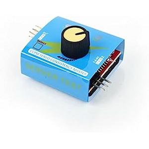
The servo require a type of pulse , PWM, (Pulse Width Modulation) with a duty cycle of about 4% to 10%. If your interested , I can help you design one that will work, or I can steer you to a device called a servo-tested that will do the it for you without a micro-controller. See this photo , you cn find it on Amazon.com and just search for CCPM Servo-tester. They're really cheap, 3 for $9 us.
Let me know if I can be of any help with your project.
Regards,
LouisR
LouisR
@inst-tech @davee Did you read the beginning of the topic? The circuit is Bill's from his 555 video.
First computer 1959. Retired from my own computer company 2004.
Hardware - Expert in 1401, and 360, fairly knowledge in PC plus numerous MPU's and MCU's
Major Languages - Machine language, 360 Macro Assembler, Intel Assembler, PL/I and PL1, Pascal, Basic, C plus numerous job control and scripting languages.
Sure you can learn to be a programmer, it will take the same amount of time for me to learn to be a Doctor.
Hi @keknor,
Measuring the values of resistors in circuit is always tricky because there will be other parts, in your case the 555 in particular, that are in parallel, so they nearly always read less than the resistor alone would read on the bench.
Admittedly, if a resistor reads (allowing for tolerance) higher than the printed value, then you have a prime suspect for replacement, as two (or more) resistors in parallel should always read less than the lowest one, but that is a very rare find, unless you start repairing old equipment.
But 99.9% of the time, reading low simply means there are other parts in parallel.
In general resistors and capacitors, providing they haven't been overheated (which is usually obvious by colour changes, etc. or mechanically traumatised, again usually apparent, do what they susposed to do. One notable exception being electrolytic capacitors that can dry up and age, especially in electronic boxes that run fairly hot, like power supplies.. but even these often show (but not always) show swelling or other signs of distress.
However, checking continuity ... i.e. if two points are supposed to be connected, do they actually show zero Ohms between them, with a meter is often useful if the circuit has just been assembled. It is so easy to forget to add that last wire or to connect it to the wrong pin!
---------
Louis (@inst_tech) has a better idea of what you are trying to do, so hopefully he can help your project out.
-----
Soldering is a technique we all struggled with at first ... albeit some of us (including me) started so long ago, our early practice isn't even a memory any more. In addition, parts are continually getting smaller, so new tricks have to be learnt. There are some good tips on YouTube ... as with the Internet, not all that is there is good, but if you watch a few, you will soon begin to see the better ones.
Certainly you need a clean soldering tip, make sure the surface of the wires, tracks, etc. are clean, add some flux, and don't carry the solder to the joint on the tip ... bring the tip and the solder together at the joint, so that the flux in the solder works on the joint, cutting through the surface layers to make a good joint.
And as for bending wires to hold the components, before soldering, the main problem is that it can be really hard to remove them later if you want to make a change. Sometimes a slight angling of the wire to stabilise it whilst the solder cools works well, whilst still being reasonably easy to remove later if required.
Good luck, and I hope your project goes well, Dave
Thank you all for the good advices!
I just lost my reply by pushing "Add reply"
Here is a short version:
Cirkuit from Dronebot Servotester copied into Tinkercad. Here I adjusted resistors to get slow motion and about 45 deg. rotation. Circuit built on a perfboard with copperstrips. I have 5 volt on the board. Also 5v in and out of the 555 timer and the servo. ON/On swich have onlu 0.19V one way and 0,30V the other way. There are no leakage between neighboring copperstrips (OHM measured)
I now suspect 555 timer is faulty?
My project is described in my blog. Scroll down a bit to se my challenge with a travesse inside a barnlike building.
Hi @keknor,
A quick tip ... if the forum eats your reply when you try to post it, don't panic ...at least not yet.. there is a cunning plan!
It usually happens when you haven't logged on for a while .. and then you have to log back in.
-----------
Ideally ... BEFORE you hit ADD REPLY, click Save Draft and Preview, which are just below ADD REPLY on the left. Check the preview is up to date ...
if it isn't up to date...then it will eat at least part of your work
So do a Copy and paste of your text into a local file on your machine ... that you can use later to paste back in to forum, if and when ADD REPLY fails.
--------
If ADD REPLY has already failed, then log back in and go to the bottom of the Leave Reply Section..
Click on "Revisions", between Preview and Save Draft
With luck it will produce one or more windows just below, with your text ... and you can now click "Restore", to bring it back into the editing box.
The bad news is it may not be all of your text ... but some recovery is better than none. Hence, the recommendation above.
--------------
By the way, if you ever send private messages across the forum, this recovery isn't available. Save a draft of your text before hitting Send!!
---------
Hope this is helpful for the future, Dave
@keknor I checked out your blog..pretty neat! Now that Ron, @zander pointed out that your project was based on Dronebot workshop video, I see what your trying to do.. What I don't understand is why you used the resister values of 470k, 20K, in the timing circuit because in Bill's video, the values are 33K,68K, and 10K. In my simulation program is shows it should work..
LouisR
I have now aquired some sockets for the 555 timer (etc). I have replaced the 555 timer and soldered in place the new socket. Onto that I hav pushfitted another unused NE555 timer. But alas, no reaction on the servo. As far as I know i have made the circuit identical to the Tinkercad version I linked to in my former reply. So I am really stuck. Any ideas?
@keknor If you are positive all solder joints are ok, then I would build the same circuit on a breadboard and using a meter or scope start tracing. If that is a problem, build a simpler circuit on the breadboard to prove the 555 is ok or not. Good luck.
First computer 1959. Retired from my own computer company 2004.
Hardware - Expert in 1401, and 360, fairly knowledge in PC plus numerous MPU's and MCU's
Major Languages - Machine language, 360 Macro Assembler, Intel Assembler, PL/I and PL1, Pascal, Basic, C plus numerous job control and scripting languages.
Sure you can learn to be a programmer, it will take the same amount of time for me to learn to be a Doctor.
I have now aquired some sockets for the 555 timer (etc). I have replaced the 555 timer and soldered in place the new socket. Onto that I hav pushfitted another unused NE555 timer. But alas, no reaction on the servo. As far as I know i have made the circuit identical to the Tinkercad version I linked to in my former reply. So I am really stuck. Any ideas?
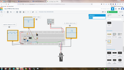
@Keknor, As @Zander (Ron) has suggested would be the first thing to do, that is, bread board the circuit and test it there to make sure all the components are good..This is where a cheap oscilloscope comes in handy to see the pulse wave form. Alternately, a digital vom that has a frequency function can be used to probe pin 2 and pin 3 of the 555. this should indicate a frequency of around 25.5Hz for the 10K, 470k, and .1uf capacitor in the timing circuit, and 28.26Hz in the 20K, 470k, and .1uf capacitor. The pulse width of the on time from the collector will vary from o.693mS to 1.38mS And will look similar to the following:
I hope this is helpful to you, but if not, let me know what you need in the way of explanation of the tinkercad screenshot.
Regards,
LouisR
LouisR
Thank you again for all advice.
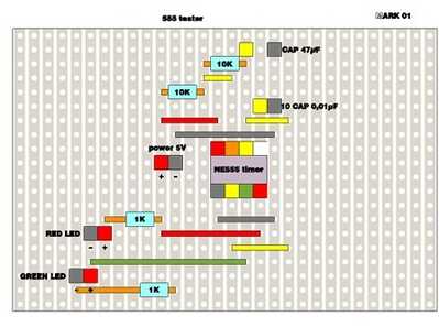
I found this on the internett: 555 Timer IC Testing Circuit and Its Working (electronicshub.org)
I made it in Tinkercad:
and on the perfboard.
and sketchup
In Tinkercad the leds blink green - red - green etc.
But on the perfboard only the green led lights continually.
I have tested five new NE555. Same result with all.
If my circuit is correct on the perfboard, is it possible that all NE 555 are faulty?


