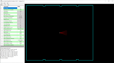
I thought that you might find the section V. Discussion interesting. They discuss the second experiment as lifting one of the constraints from the fitness function to transform it into a “general survival criterion”. Looking for a ‘richer’ interaction of the robot with the environment.
Tom
To err is human.
To really foul up, use a computer.
I thought that you might find the section V. Discussion interesting. They discuss the second experiment as lifting one of the constraints from the fitness function to transform it into a “general survival criterion”. Looking for a ‘richer’ interaction of the robot with the environment.
Tom
Yeah! I saw that. Just
Fitness = V * (1-i) or in my case Fitness = V * s;
I wanted to fire off all the above work while the first experiment changes were still fresh, but I do need to sit down and digest all that latter experiment. I'm sure it'll have some useful information moving forward into other tasks I need.
3 lines of code = InqPortal = Complete IoT, App, Web Server w/ GUI Admin Client, WiFi Manager, Drag & Drop File Manager, OTA, Performance Metrics, Web Socket Comms, Easy App API, All running on ESP8266...
Even usable on ESP-01S - Quickest Start Guide
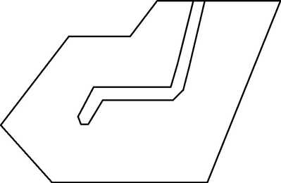
Using the same weights have you tried different starting points and also using the same weights tried different layouts. For example the weights that result in your last demo of the robot travelling around the center walls what would happen if you used this layout?
I'm just getting started studying section IV and the results seem miraculous considering the fitness doesn't even hint at such goals. It is merely that the input nodes and ANN is geared to handle the extra inputs. I will certainly have to see if I can simulate their test conditions and reach those goals.
I was trying to work out that their 102 Chromosome length. I finally got, it, but I'm I'm not exactly sure how to handle the Recurrent Connections. I see the arrows that loop back to themselves on the hidden layer, but I'm not exactly sure I see how that translates into code. I'm guessing the outputs of the hidden layer are run through a different 5x5 matrix that outputs back to the hidden layer, but that sounds like an infinite loop to me. My Goldberg book doesn't shine any light on the quandary. Time to dig on the Internet.
Another thing... they got rid of the velocities of the previous time step being used as inputs. So it calculates the outputs for the motors, and uses them in the fitness calculation, but they're not used as inputs. The ANN doesn't know what speed the bot is doing. At least, its not using the velocities to make decisions. Hmmm.
I thought that you might find the section V. Discussion interesting.
Finally getting down to V. Discussion
I can see why... it directly addresses my attempt at detailing the fitness function being one way to do it, but as reflected above, it assume the experimenter (me in this case) can fully qualify the interactions. As the scope of the problem intensifies, this may be impossible. That they actually made it simpler and just gave the bot the components to sense its environment AND that the environment gave it the feedback necessary, it achieved some remarkable results!
3 lines of code = InqPortal = Complete IoT, App, Web Server w/ GUI Admin Client, WiFi Manager, Drag & Drop File Manager, OTA, Performance Metrics, Web Socket Comms, Easy App API, All running on ESP8266...
Even usable on ESP-01S - Quickest Start Guide
I think it is about time to start migrating the AI onto the real InqEgg. I'm feeling pretty good about the results and their correlation to the ACAA paper at least considering within the range of my approximations for inertia, and friction. I'll start off with just putting on the code required to use the matrices generated on the virtual version. That shouldn't involve that much code. But first...
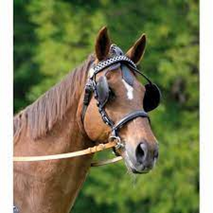
I need to reset the virtual model to use the ToF sensor pattern of rays instead of the ACAA pattern. Unfortunately, whereas the ACA has about a +/- 80° vision out front and two looking backwards, it was able to handle tight quarters. InqEgg's ToF has none in back and about +/- 22° out front. Kind of like horse blinders.
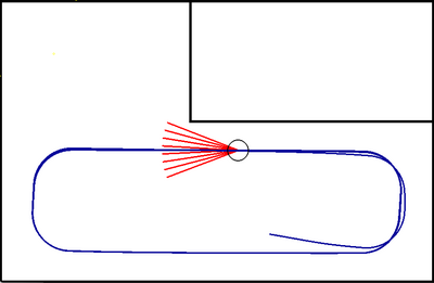
Fortunately, it has far further range so, it can see and plan ahead. I first tried it on the ACAA arena and no luck. It could not complete the course. As this is just a proof of concept to correlate the virtual with the real InqEgg, I'll start out with a simpler, larger arena. The first is to simply run here in portion of my office (1800 x 1500 mm). I was able to many great Genome candidates and the although the best Fitness was not the fastest, it was a good, solid candidate. Here is the best candidate that pretty much utilizes the whole arena, has a top speed of 1119 mm/s and completes a lap in about 8 seconds.
I need to add the code to run it on the InqEgg and to see if I can write code to send the Genome over via WiFi from the virtual program. I'll report back when I start getting results (good or bad).
3 lines of code = InqPortal = Complete IoT, App, Web Server w/ GUI Admin Client, WiFi Manager, Drag & Drop File Manager, OTA, Performance Metrics, Web Socket Comms, Easy App API, All running on ESP8266...
Even usable on ESP-01S - Quickest Start Guide
Trying out several settings in the Auditorium 15m x 15m. Setting anything below 500mm range on the ToF sensor, and it runs into the wall. Even 500mm gives only ~2mm clearance. 3000mm on the ToF gives more leisurely arcs in the corners.
ToF range = 500mm Vmax = 1025 mm
ToF range = 3000mm Vmax = 1189 mm
3 lines of code = InqPortal = Complete IoT, App, Web Server w/ GUI Admin Client, WiFi Manager, Drag & Drop File Manager, OTA, Performance Metrics, Web Socket Comms, Easy App API, All running on ESP8266...
Even usable on ESP-01S - Quickest Start Guide
When it hits a wall the question is: should it turn left or right? In the case below it always turn left. Usually with a sonar based hard coded solution the robot looks left and right to decide which way to turn next. This would require more layers of neurons to analyze the situation using outputs to motors that swivel the TOF detector (or rotate the robot) and act accordingly.
With the limited visual field of your single TOF camera there are situations like the one below where it cannot spot things like a change in direction and will simply keep going until it gets another reading. Losing contact with the wall (no readings) the robot would need to rotate to see if it can make contact again.
The funny turns in your videos is I think is due to the distance measures changing when the robot turns because they actually increase or decrease even though the actual distance of the center of the robot to the wall is constant.
The transition of using the virtually derived Genome on the real InqEgg was a bust... so far. It simply sits on the floor and chatters. Inspecting the code while running, I found that stepper motors could not handle the simplistic fitness factor driving the bot. As can be seen (here again)
Fitness = V * (1 - sqrt(dv)) * s;
- V = average velocity of both wheels
- dv = difference in velocity of both wheels
- s = distance to closest obstruction
Basically, I determined, this fitness equation has a lead foot. It sees an open road and it throttles to the floor. The stepper motors can't overcome the inertia of the bot so suddenly and start losing all the steps... IOW chattering and no speed.
The ACAA paper bot uses DC motors with encoders. When the throttle is floored on it the DC motor drivers simply dump full voltage/current into the motors and the motors eventually get up to speed. The AI handles this acceleration phase transparently.
Also, the cheap stepper motor drivers I'm using have no way of noting that the motor is missing steps.
I took the bot into the auditorium and did some more testing. I believe I can substitute the longitudinal acceleration integrated over time to determine speed the bot is actually going and feed that into V instead of the velocity I'm telling the steppers to do. I can use the Gyroscopes Z axis data to likewise substitute for dv.
On the virtual bot, I'll need to incorporate maximum accelerations into the Fitness equation. I did some ball-park tests and found that the bot could accelerate to 1500 mm/s in about 4 seconds without missing steps. If I tried to go to 2000 mm/s, I could not manually control is subtly enough to keep it from start missing steps on one of the motors and the bot spins to a stop. If I tried to manually accelerate it quicker than the 4 seconds, it also went into the death spiral.
I haven't really wrapped my head around all the data, but I'm thinking a fitness function like the following might create a better Genome that is more compatible with the real bot.
Fitness = V * (1 - sqrt(dv)) * s * (1 - a/anom);
- a = acceleration from the sensor
- anom = 1500 mm/s / 4 seconds = 375 mm/s/s.
Since the acceleration will have to be incorporated into the inputs and Genome, the Genome will go from 20 elements to 22 elements.
More to come...
3 lines of code = InqPortal = Complete IoT, App, Web Server w/ GUI Admin Client, WiFi Manager, Drag & Drop File Manager, OTA, Performance Metrics, Web Socket Comms, Easy App API, All running on ESP8266...
Even usable on ESP-01S - Quickest Start Guide
Hi Inq,
re: The stepper motors can't overcome the inertia of the bot so suddenly and start losing all the steps... IOW chattering and no speed.
I would guess this type of situation may be typical of many cases, and it leaves me wondering what the approach should be attempted or desired.
On one side, the present situation, where the machine is given authority to do something which can be predicted to be useless, and in a 'real machine', might even be catastrophic.
If you buy a car (say), intended for normal driving on public roads, should flooring the accelerator from standstill cause the vehicle to try to act like a badly designed dragster, probably fail in its purpose of smoothly accelerating, and possibly damaging it, or should the vehicle management system try to ameliorate the situation, to make the vehicle easier and safer to drive?
I confess to not having a 'sporty' vehicle, though even a small engine can result in more wheelspin than forward progress, but I guess those with deeper pockets also make use of traction control, ABS breaking, and so on, in preference to a 'raw' machine that attempts to do exactly what what the pedal position is implying, in spite of physics having the last laugh.
I do not intend this to be a discussion about ethics, or civil liberties, etc., but just suggest that for the majority of customers, a vehicle which is reliable, easy and comfortable to drive, and forgiving of mistakes, may be less dramatic, but probably will probably sell quite well.
So, is it wise to expect an AI system to figure out how to drive a raw machine, or is it better to start with a predefined control system, whose acceleration (say) is 'pretuned' and 'scaled' to keep it within the confines of what it can actually do? I should say, in the latter case, I am not just thinking of a simple limiting function, but of a more sophisticated function that will always have '100%' as the maximum possible at that moment.
I tend towards thinking the latter, because it enables the AI system to 'concentrate' on the main task, but it does have the disadvantage of limiting the AI's options.
Best wishes, Dave
If you buy a car (say)...
90% of the time, I'd like a Tesla (or equivalent) to safely keep me out of trouble or to drive me home or somewhere when I really can't or won't be all that attentive. But I also am of the group, that there is no replacement for cu-in. I don't want any traction control. The top has to come off and it has to have a stick to row the gears. Hitting the perfect Apex it on the order of the perfect golf swing... something to aspire to.
So, is it wise to expect an AI system to figure out how to drive a raw machine, or is it better to start with a predefined control system, whose acceleration (say) is 'pretuned' and 'scaled' to keep it within the confines of what it can actually do? I should say, in the latter case, I am not just thinking of a simple limiting function, but of a more sophisticated function that will always have '100%' as the maximum possible at that moment.
I tend towards thinking the latter, because it enables the AI system to 'concentrate' on the main task, but it does have the disadvantage of limiting the AI's options.
I'm not quite sure I'm getting all your nuances here. You might need to add more words for clarification. I can't tell if you're referencing my two cases in the previous post (accelerometer/gyro testing vs using a constant in the fitness) or have some broader/deeper meaning.
If I understand your differentiation... at the moment, I'm leaning toward the former. At least, until I find it causes to much burden on the bot keeping it from completing any primary tasks.
My current, thought process goes something like this:
I wasn't sure the virtual bot was going to be worth the effort. But after using it, it has become invaluable. I expect it to be able to get past the preliminary stupid phase of a genetic evolution. Instead of head banging and twirling due to the early Genome's being totally random data, a real bot might start with something... kind-of close. But what has really proven to be more valuable is that I can see trends changing in seconds while evolving that would easily be missed over a two day evolution of a real bot. I can then quickly change parameters, try new fitness equations, use different starting locations / orientations and watch the affects it has on the evolution process or end results. I have seen in minutes and hours of use what I could not possibly try in weeks and months. Much less assimilate the subtleties that would transpire over such spans of real-time.
In the context of your post, to make the virtual bot mimic what I'm seeing, I am trying two different things. My first used the ACAA fitness equation and let it spit out what it wants for the two velocities and the GUI displays the bots updated position/orientation. Most of the videos show those results.
I then added a post calculation step that basically says, this is the speed change you want, but this is what you actually get using a crude inertia equation. Although, the changed velocities are used in the next time step's calculation, I'm not seeing a learning from that change. The same virtual life evolution that worked fine with many great working Genomes, now starts running into walls on every Genome. It never learns.
The second method that I'm now starting on is to incorporate the same crude inertia calculation directly into the fitness equation. I'm theorizing this will start down scoring certain Genomes and letting others (being slower before) are now promoted... because they accelerated slower.
This sounds kind of contrived, but it is what's required in the virtual bot. In the real bot, I do want it to be more as you put it...
to figure out how to drive a raw machine
I'm not quite sure what will be the final method, but the goal is to have the fitness equation able to detect the difference in expected velocity and observed velocity and adjust accordingly.
- I see this necessity to get closer to 100% of the performance.
- I've noted that as the LiIon batteries go from 16.4V to 12.0V the steppers start missing steps at different accelerations. Say at 16.4V, I might accelerate to top speed in 3 seconds, it might take 4 seconds to keep it from missing steps when at 12V.
- It'd be nice to put the same equations / starting Genome on say a completely different bot and have the Genetic Evolution figure out the differences on its own. For instance, the rated steppers on Inqster project a zero to 25 mph in under two seconds. I expect the learning will come up with far different Genomes.
As I casually mentioned, when the bot is asked for too drastic a speed change, one of the steppers starts missing steps and goes to zero speed while the other is still moving spritely. It start spinning out of control. Manually, I have to stop the bot and restart accelerating. Hopefully, with the sensors available on the bot already, I can detect this before it starts. Kind of like ABS braking. It notices stoppage of a spinning wheel before it stops. This might take more AI/MPU power when learning, but it should not be all that much more costly after put into use.
... at least that's what I'm hoping for.
Realistically, I expect you'll be right, that I'll need to pre-tune things to stay say... 80% of the worst, low-voltage conditions.
... hope for the best, expect the worst.
3 lines of code = InqPortal = Complete IoT, App, Web Server w/ GUI Admin Client, WiFi Manager, Drag & Drop File Manager, OTA, Performance Metrics, Web Socket Comms, Easy App API, All running on ESP8266...
Even usable on ESP-01S - Quickest Start Guide
Hi @inq,
I guessed you (personally) might be more of an open top, straight through exhaust and foot to floor type .. at least in your dreams! Perhaps you have the space, etc. to make it a reality, whilst on my side of the pond, just during the time I have had a driving licence, the number of cars has almost doubled, and the number of speed cameras increased to the extent that makes me feel like I am in an extended film studio, traversing an infinitely long gauntlet of legal and physical hazards.
Admittedly, age now means arriving safely and (law breaking) ticket-free is my one and only aim, but I am reminded of the claims (which I can neither prove or disprove) that a modern jet figher plane is practically impossible to fly without the computers controlling all of the flight surfaces, fuel flow and so on.
I sense that technology means even the racing drivers are 'content' to let the computers figure out the best options in terms of fuel flow, braking force, etc., leaving the driver to point the vehilcle in the right direction and use their right foot to 'indicate' as to whether they want to speed up, slow down, or keep the present speed. The rationale being, the driver with the computer's assistance will be quicker than a driver with 'raw' controls.
Hence, whilst I am not claiming to have included any subtle nuances, I was suggesting provision of 'hard coding' and sensors to provide an interface between the stepper motors' driver chips and the outputs of the AI system as a pragmatic choice. However, I was not suggesting a simple limiting function, making it as agile and speedy as milk float (UK 'traditionally lead-acid battery powered van for delivering bottles of milk to the consumers' doors), but rather a smarter interface, so that when the AI asks for full power (say), then it gets the fastest acceleration the bot/vehicle can achieve, taking into consideration, battery voltage, wheel traction, and so on. Hence the AI system has the authority to drive into wall at full power and full speed, but should not became a chattering nervous wreck at the starting position, nor should the tyres be converted into smoke on the first lap.
--------
Of course there might be a handy mix and match compromise. Have two AI systems, one still does the driving, and the extra one handles the technical stuff, like fuel flow, breaking force and so on.
In principle they can be trained independently, the 'extra' one first, of course.
Furthermore, when they are both trained, it might well be possible to coalesce them into a single machine.
--------
I think your simulations are great, but as you suggest, they must include realistic 'limitations', so that the AI system can learn to work around them.
------------
I hope that is useful .. perhaps there is little that is new, or even 'not obvious', but it is the best I can do for now.
Best wishes, Dave
that a modern jet figher plane is practically impossible to fly without the computers controlling all of the flight surfaces, fuel flow and so on
I used to work for McDonnell Aircraft. At the time they were building F-15, F-18 and AV-8B. I can certainly attest that the AV-8B simulator flew very nicely until the operator simulated a multi-computer failure. I was in the virtual mud in seconds. The SOP was punch if that actually happens in reality. 🤣 It certainly gave credence to English aviators and your all's Harrier. It had no flight computers. The pilot handled all modes hover, transition, forward flight.
The rationale being, the driver with the computer's assistance will be quicker than a driver with 'raw' controls.
Or without the driver...
3 lines of code = InqPortal = Complete IoT, App, Web Server w/ GUI Admin Client, WiFi Manager, Drag & Drop File Manager, OTA, Performance Metrics, Web Socket Comms, Easy App API, All running on ESP8266...
Even usable on ESP-01S - Quickest Start Guide
After trying to incorporate the acceleration factor into the fitness equation, the results were less than satisfactory. Stepping back, I realized that the ACAA Paper bot, using DC motors and encoders is also telling its motors to go from zero to full speed in one step also. It is merely the mechanical limitations of inertia that keeps it from actually going from zero to max speed instantly.
I've re-evaluated my crude Inertia calculations and have improved them some. Before, they just limited the change in speed of each wheel. Now:
- The bot speed is calculated before and after each time step
- Acceleration calculated of what Genome wants it to do.
- The acceleration is capped at a constant that was calculated from the physical manual tests performed in the Auditorium. The wheel speed changes are then attenuated by ratio of required acceleration / Genome desired acceleration.
- Also, the decelerations were allowed to be twice the accelerations as was observed in the manual tests.
An evolution was carried out using these results in a slightly improved auditorium model. I've added the wall column obstructions.
I can not model things like chair legs in the virtual model as the ToF rays are just line segments. If they don't actually hit the tiny chair leg, they won't be noticed. The real ToF senor works by a region, so I suspect it will see real chair legs. However, I am dubious whether it will successfully navigate around all these extensive obstructions you can see in the real picture. We'll see.
After running the Evolution, the best fitness solution was able to navigate around the room, but it was neither the fastest nor the best at circumnavigating the perimeter. I used the lapping search feature to find candidates that did a better job. Out of those, the best for what I want to accomplish is this one. The video shows the bot moving around the 50 feet x 60 feet room at max program speed just so paint drying doesn't bore you. At the end (0:47) I do slow it down to actual speed to get the relative flavor. It takes the bot about 100 seconds to make one circuit of the room.
3 lines of code = InqPortal = Complete IoT, App, Web Server w/ GUI Admin Client, WiFi Manager, Drag & Drop File Manager, OTA, Performance Metrics, Web Socket Comms, Easy App API, All running on ESP8266...
Even usable on ESP-01S - Quickest Start Guide
I've re-evaluated my crude Inertia calculations and have improved them some.
It would be neat if a genetic algorithm could evolve those types of calculations itself.

