Just as you can break a program down into meaningful and independent functions you can do the same with electronic circuits.
So for example your button function should be independent of your beam break function and they should not interact. Each servo circuit is independent of the other servo circuits. This should be reflected in the software.
I was also going to mention powering the servos independently of the Arduino. As mentioned here "It is not a good idea to use the Arduino 5v pin to power your servos. Electrical noise and 'brownouts' from excess current draw can cause your Arduino to act erratically, rest and/or overheat."
https://learn.adafruit.com/16-channel-pwm-servo-driver?view=all
It is very hard to trouble shoot via a series of posts. I am sure we could get it working very quickly if we were actually there 🙂
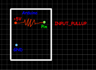
First I think your button is wired in pull-down mode, while in your code you use it with INPUT_PULLUP.
Pull-down : https://www.arduino.cc/en/tutorial/button
Pull-up (done internally because of INPUT_PULLUP) : https://www.arduino.cc/en/Tutorial/DigitalInputPullup
3 ways to wire a push button with corresponding code :
https://www.brainy-bits.com/arduino-input-pullup-tutorial/
Then I think we need to know more about your IR beam emitter+receiver.
Eric
Looks like we have a new code guru already. ?
DroneBot Workshop Robotics Engineer
James
I ventured in to another forum yesterday when I started my repost of my code I was working on and before I messaged @robo-pi (honestly wasn't cheating on you guys!!!) I am just on a mission on learning... so fyi only one person replied to me there... I guess I must smell... lol. any way he brought up the concept od the state machine and I am not fully getting it but I will post what he gave... I have not had a chance to run it yet but for the good of order here it is:
No No No... this upon a suggestion for another forum early on... I can take any credit... still learning and trying to figure out the semantics
Update for everyone... I moved the orientation of the resistor and the ground wire and now it works... who knows... I know resistors don't have polarity... right?
@casey
so I do have the PCA9685 on it own power supply now as well... would the IR Beam Break Need a separate power supply too? or can that tap of of the 5v of the arduino?
I moved the orientation of the resistor and the ground wire
Check those links in my post above ?
Eric
would the IR Beam Break Need a separate power supply too? or can that tap of of the 5v of the arduino?
I think it all depends on their specifications, so give us what you have about them (datasheet, manufacturer+part number, whatever...) and we can check waht they need.
Eric
Ok, from page 5 : it seems you can wire them to the Arduino and each will use around 20mA. The most important is that the receiver has the same voltage reference as the Arduino, while th emitter could be powered from another power supply if you wish. Be sure to use INPUT_PULLUP for the receiver digital pin, or use a 10K resistor.
First up you'll need to power the transmitter. Connect the black wire to ground and the red wire directly to 3.3V or 5V
power. It will draw 9mA from 3.3V (lower power) and 20mA from 5V (better range)Next up you'll want to connect up the receiver. Connect the black wire to ground, the red wire to 3.3V or 5V
(whichever logic level you like) and then the white or yellow wire to your digital input.Note that you do not have to share power supply ground or power between the two, the 'signal' is sent optically.
The receiver is open collector which means that you do need a pull up resistor. Most microcontrollers have the ability
to turn on a built in pull up resistor. If you do not, connect a 10K resistor between the white wire of the receiver and the
red wire.
Eric
@casey
Ah-So! They are a little wider that they are long, or looking at it another way they are longer than they are wide.
SteveG
so let get this straight... I could put a 10K between the signal wire and the 5v wire? or just do a INPUT_PULLUP in the code can you have two pullups in the code (I am thinking yes just because there a two different states using it at different time) if not then the 10K is fine
so first of al to assign the IR to a pin would I write:
int lastButtonState;
const byte buttonPin = 2;

// IR Breakbeam sensor

const byte sensorPin = 4;

like the button pin?
ok... does it matter what you call the "int" trying to learn the semantics!!!
Sorry I don't get the meaning of your question ?
Eric


