Hi,
I'm working on the Mecanum project and I have a couple of beginner questions about the filtering capacitors.
The video said that there was a capacitor "across the motor voltage line" on the H-bridges. Does that mean that one pin from the capacitor is connected to the motor voltage and the other pin connected to ground, or that the pins are "inline" with the wire. I (obviously) have almost no experience with capacitors. I think I've seen them used with one pin connected to ground and the other to the positive, but I couldn't quite make out the connections in the video.
Also, any information about the required or recommended capacitance for the capacitors?
One last question: If I set everything up on a breadboard and put the capacitor in place, is it likely that I'll see the impact of having the capacitor added?
Any help is greatly appreciated!
Thanks.
Davidl
@davidl Do you not have a schematic? That will tell you how it is connected.
First computer 1959. Retired from my own computer company 2004.
Hardware - Expert in 1401, and 360, fairly knowledge in PC plus numerous MPU's and MCU's
Major Languages - Machine language, 360 Macro Assembler, Intel Assembler, PL/I and PL1, Pascal, Basic, C plus numerous job control and scripting languages.
Sure you can learn to be a programmer, it will take the same amount of time for me to learn to be a Doctor.
The video said that there was a capacitor "across the motor voltage line" on the H-bridges. Does that mean that one pin from the capacitor is connected to the motor voltage and the other pin connected to ground, or that the pins are "inline" with the wire. I (obviously) have almost no experience with capacitors. I think I've seen them used with one pin connected to ground and the other to the positive, but I couldn't quite make out the connections in the video.
Also, any information about the required or recommended capacitance for the capacitors?
One last question: If I set everything up on a breadboard and put the capacitor in place, is it likely that I'll see the impact of having the capacitor added?
Yes, you should always put a capacitor across the motor input supply on the board (+ve to motor + and - to GND).
The reason is to isolate the driver from spikes and provide a small reservoir to try to keep the voltage supply constant.
The only way you're likely to notice any benefit from using the capacitor is if disaster strikes. Hopefully that won't happen.
Oops, forgot to say that the capacity depends on the motor and driver, but you should start from about 100uF and up.
Anything seems possible when you don't know what you're talking about.
@zander Hi Ron, I should have included a link to the video:
THis is about the point where the capacitors are discussed. Unfortunately I don't have a schematic.
Thanks
@will Hi Will,
Thanks for the response.
One follow-up question to make sure I understand. In the video
it sounds like the capacitors are across the "motor voltage line". I was assuming that the "motor voltage line" is the wire connected to the VM pin (based on the pin table here: https://learn.sparkfun.com/tutorials/tb6612fng-hookup-guide/all . Is that the "+ ve" to motor wire you're referring to?
Thanks!
David
@davidl What is the exact time in the video that you are referring to?
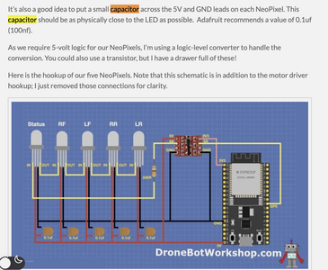
Also, you are far better off using the article for reference, the video is good for the introduction of the project and as eye candy, but the instructions to build are in the blog. Here are some screenshots. The first pic shows you where to click the 'more' link on the YT page.
The next pic shows you the now revealed link to the article.
In the article, the capacitors are discussed, and a wiring diagram is shown in the last pic
First computer 1959. Retired from my own computer company 2004.
Hardware - Expert in 1401, and 360, fairly knowledge in PC plus numerous MPU's and MCU's
Major Languages - Machine language, 360 Macro Assembler, Intel Assembler, PL/I and PL1, Pascal, Basic, C plus numerous job control and scripting languages.
Sure you can learn to be a programmer, it will take the same amount of time for me to learn to be a Doctor.
Your motor driver will have pins identified as the input for the power source's +ve and GND wires.
The electrolytic capacitor has 2 lead wires, the longer one is the positive side and the shorter one is the negative side. The negative side usually has a white stripe up the side of the case as well.
Put the capacitor across the driver's two pins for motor + and GND with the + lead from the capacitor to the + pin for the voltage and the - lead from the capacitor to the GND pin of the driver board.
Anything seems possible when you don't know what you're talking about.
@zander Sorry, I meant to include the timestamp of 41:30 into the video. I have to avoid posting after 8:00 at night or before I have coffee in the morning. Hopefully that link starts at about the 41:30 mark.
Thanks for pointing me to the part of the article that talks about the NeoPixel capacitors. I've been using both the article and video, but mostly the video. I didn't see anything specifically about the capacitors for the motor voltage, but t seems reasonable that the motor voltage capacitor would be connected in the same way (one pin to the 5v and one pin to GND) as the NeoPixel capacitors.
Is that correct?
Thanks again!
@davidl Good catch. Those 5 capacitors are NOT mentioned in the article.
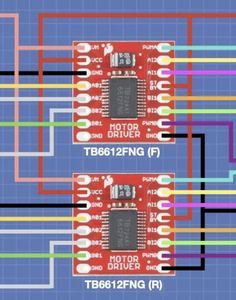
Everything @will said is correct, but that only covers the two drivers. There are 3 more capacitors to connect as I described above.
I am posting 2 pics. In the first, there are 2 Electrolytic caps needed, one per board. Connect the + side to the VCC pin top left 2nd down and the - side to G top left 3rd down.
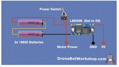
There is a total of 3 caps for pic 2. A catalytic between G and the main 5V power which is the leftmost red and G in the middle. The far right needs a pair of caps, another catalytic 100uF and a ceramic 10nF. OK?
First computer 1959. Retired from my own computer company 2004.
Hardware - Expert in 1401, and 360, fairly knowledge in PC plus numerous MPU's and MCU's
Major Languages - Machine language, 360 Macro Assembler, Intel Assembler, PL/I and PL1, Pascal, Basic, C plus numerous job control and scripting languages.
Sure you can learn to be a programmer, it will take the same amount of time for me to learn to be a Doctor.
@zander Thank you, this is extremely helpful!
I think the only thing I'm not clear on now is the two capacitors that go on the right side of pic 2. For the electrolytic, I assume + will go to the 5v and - will go to the ground. For the ceramic (not polarized if I understand correctly) one pin will go to 5v and the other to ground. Am I understanding correctly that there are two capacitors between 5v and ground on the input to the buck converter?
Thank you for your patience!
David
D
@davidl Yes, 2 capacitors. Note the values. The ceramic is 10 NANO farads this is to deal with high-frequency noise. I am not 100% sure that is the 'best' value. Maybe @davee will chime in with an in-depth answer and some math to determine what is needed. Similarly, the catalytic I think, is 100 or 1000 MICRO farads to deal with the ripple. Again, maybe @davee will flesh out that value as well.
I do know the reason for two is that one filters high frequencies and the other is more for ripple in that it acts as a sort of buffer to even out the ripple. Clear as mud?
First computer 1959. Retired from my own computer company 2004.
Hardware - Expert in 1401, and 360, fairly knowledge in PC plus numerous MPU's and MCU's
Major Languages - Machine language, 360 Macro Assembler, Intel Assembler, PL/I and PL1, Pascal, Basic, C plus numerous job control and scripting languages.
Sure you can learn to be a programmer, it will take the same amount of time for me to learn to be a Doctor.
Thanks for the follow-up! I'm glad you pointed out the "NANO" farads. I probably wouldn't have noticed that.
I would like to see the math, but I suspect it's well over my head.
Thanks again!


