hi all,
I'm looking for a neat and tidy way to configure four outputs from a single output, the power source is a 36V , 5A switching power supply, one output will go to a Buck converter which will have an adjustable output, each or the other 3 will be connected to separate USB modules with outputs of 5V, 9v , 12V .
I'll explain the rest of the project later but for now all I'm asking is how to neatly (and safely) wire 3 outputs from one single source in parallels. total amperage will not exceed the 4 Amps .
Connecting, forcing the twisted ends of 4 lengths of wires (14AWG black and 4x 14AWG Red) inside the tiny positive/negative holes of the output maybe hard to do, I've managed two but never 4.
I know this is a basic /run of the mill question but most of you at some point might have faced the same scenario in the past , so how did you do it?
Ken from Peterborough
@will @ddistrbd1 Controversial. If you look closely, you will see the point of contact is very small. If the amperage is very small, then it is acceptable but I would not use it on a 5A DC circuit. The gold standard is twisted and soldered covered in double-walled with adhesive heat shrink, followed by proper wire nuts with knife-edge interiors that groove the wire and create a fairly decent surface area. The cheap wire nuts use round interiors with much less copper in contact.
As an electrician, I would not use those for what sounds like 36VDC at 5A. If it was 36VAC at 5A, it would be marginal.
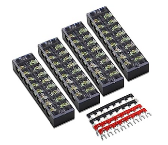
HOWEVER, the OP question needs to be clarified. He needs to post a schematic. If it is a simple one wire into 4, then the terminal strip @rcc1 proposed is the best solution, but size it for 14AWG and use crimp-on ring connectors. Get a professional crimper. They normally come in a range of sizes for one crimper, you obviously need at least 14AWG, but without knowing your future plans I can't tell you if you need a 14, 12, 10 or a 14, 16, 18. I have crimpers up to 4 IIRC, after that, it's a hammer crimper that I used on my 4/0AWG battery cables (as thick as a man's thumb, designed to carry 400A)
First computer 1959. Retired from my own computer company 2004.
Hardware - Expert in 1401, and 360, fairly knowledge in PC plus numerous MPU's and MCU's
Major Languages - Machine language, 360 Macro Assembler, Intel Assembler, PL/I and PL1, Pascal, Basic, C plus numerous job control and scripting languages.
Sure you can learn to be a programmer, it will take the same amount of time for me to learn to be a Doctor.
@rcc1 ,Will, Ron, thank you all for your comments ,
rcc1, I thought about using a busbar connector but the ones I remembered was the white plastic ones that you daisy chained the terminals with wire , you know , the old ones from my era, then I saw the picture you posted and realized they have improved on the design dramatically. I ordered a set of 5(with 8 position screw blocks), will see if they fit in the project box.
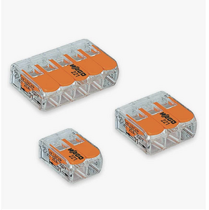
Will, I love those WAGO type connectors, in fact I have 10 of them( 2 wires in , 6 wires out), and since the space inside the box for this project is limited, they were my first choice due to their small size. but then I saw the terminal blocks LOL.
Ron, not often you are wrong but you're right again, the terminal blocks are a better fit , I am aware you don't have the whole picture of what I have in mind but you still managed to nudge me in the right direction, the size of the wire I'm planning to use is 16AWG, as I mentioned there will not be high demand on any of the outlets.
As for crimpers, I do have a a good pair and some half decent connectors, I also could use brass lugs if I need to , bought a hammer crimper last year with a whole bunch of different size copper lugs to build a resistance soldering unit, and that was the only time I used it, I forgot all about them until I read your post.
Anyhow, thank you all, you have helped more than you think you did, I am fully loaded with the parts for this project, now I'm going to build me a new power supply.
Ken from Peterborough
@ddistrbd1 I want to back up a bit. In your OP you said
separate USB modules with outputs of 5V, 9v , 12V .
USB is 5 volts. What do you really mean by 9V and 12V? If you think some innocent visitor to your house isn't going to plug their $1,500 iPhone into an inviting free charge plug which, if it is 12V will probably destroy the phone, then you are a very optimistic person who must have a great lawyer.
I assume your premise is that the power supply output of 36V will go to 3 different voltage regulators of 5V, 9V, and 12V. That part is fine just don't use a USB connector for the 9V and 12V use a DC barrel connector or similar and label them clearly.
First computer 1959. Retired from my own computer company 2004.
Hardware - Expert in 1401, and 360, fairly knowledge in PC plus numerous MPU's and MCU's
Major Languages - Machine language, 360 Macro Assembler, Intel Assembler, PL/I and PL1, Pascal, Basic, C plus numerous job control and scripting languages.
Sure you can learn to be a programmer, it will take the same amount of time for me to learn to be a Doctor.
@ddistrbd1 I want to back up a bit. In your OP you said
separate USB modules with outputs of 5V, 9v , 12V .
USB is 5 volts. What do you really mean by 9V and 12V? If you think some innocent visitor to your house isn't going to plug their $1,500 iPhone into an inviting free charge plug which, if it is 12V will probably destroy the phone, then you are a very optimistic person who must have a great lawyer.
I assume your premise is that the power supply output of 36V will go to 3 different voltage regulators of 5V, 9V, and 12V. That part is fine just don't use a USB connector for the 9V and 12V use a DC barrel connector or similar and label them clearly.
Ron ,thanks for the correction, what I meant to say was "separate modules" as well as 3 USB modules but my fingers were typing faster than what I was thinking,. so here is the clarification:
I'm planning to have 3 USB outputs( Type C , maybe also type A), as well as 3 sets of banana jack sockets/ Binding Post Terminals, 3V. 5V , 9V, .
In case you're interested, right now I am sitting at my desk testing all sorts of modules ( Step Down Buck Converter Charging Modules, adjustable buck modules, etc.) I have 6-7 lined up., before I connect any of them to the 36V power supply, I want to test them with my bench top PS to verify the actually work , what can I say I'm enjoying it all.
Talk to you soon.
Ken from Peterborough
@ddistrbd1 Ok, that sounds better.
FYI, I have many adjustable LM2596 buck/boost modules that I use for power supply applications. I often use one of those in front of a Linear Voltage Regulator. The buck/boost drops the voltage from between 1.2V and 37V to something like 4.5, 7, 14 then the LVR nails it. Those LM2596s are good for 3A, which covers most of my requirements. I have a few different LVRs, they often come in families, and 3.3V and 5V are common, and 9V and 12V are less so but easily found.
When you are done, show us your solution.
First computer 1959. Retired from my own computer company 2004.
Hardware - Expert in 1401, and 360, fairly knowledge in PC plus numerous MPU's and MCU's
Major Languages - Machine language, 360 Macro Assembler, Intel Assembler, PL/I and PL1, Pascal, Basic, C plus numerous job control and scripting languages.
Sure you can learn to be a programmer, it will take the same amount of time for me to learn to be a Doctor.
@ddistrbd1 Ok, that sounds better.
FYI, I have many adjustable LM2596 buck/boost modules that I use for power supply applications.
Yes I'm somewhat familiar with them.
Actually those are the modules I was talking about in my post, The first time I used one was in my first 24v power supply and it was a LM2596HV ,with both AC and DC input, I adjusted it to 12VDC to power the car USB Charger , but there's also another one I like: (LM2595HVS), it only handles DC input of 4.5VDC to ~53VDC as far as I know,
My linear power supply is done but the output performance was so disappointing that I did not even bother to install it in a proper box. the source of my disappointment was the weak transformer , although it was fun building it but without a bigger transformer, I couldn't justify using the $30 store bought metal box for it.
Ken from Peterborough
@ddistrbd1 Ken, there is NO such thing as an AC to DC version of an LM2596. Stop believing AliExpress BS. I have attached the OFFICIAL data sheet. There are versions to produce 3.3V, 5V, 12V, and adjustable. I have attached the datasheet.
First computer 1959. Retired from my own computer company 2004.
Hardware - Expert in 1401, and 360, fairly knowledge in PC plus numerous MPU's and MCU's
Major Languages - Machine language, 360 Macro Assembler, Intel Assembler, PL/I and PL1, Pascal, Basic, C plus numerous job control and scripting languages.
Sure you can learn to be a programmer, it will take the same amount of time for me to learn to be a Doctor.
@ddistrbd1 Ken, there is NO such thing as an AC to DC version of an LM2596.
Thanks for the info.
As a newbie hobbyist with next to zero knowledge of the field I have great amount of respect for you, Dave ,Bill others and totally accept your comment .
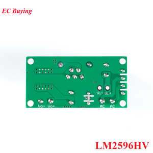
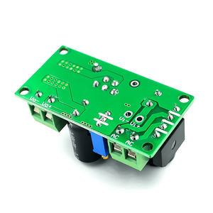
This is the back of the HV version with AC + in AC- in, can't remember if I even tested it with my AC transformer, so you are saying I shouldn't. it will destroy my module? I really don't want to take a chance and blow up my last module.
Ken from Peterborough
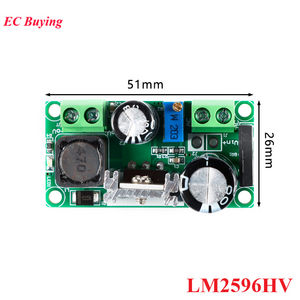
@ddistrbd1 Show me the other side, doesn't look like a LM2596
First computer 1959. Retired from my own computer company 2004.
Hardware - Expert in 1401, and 360, fairly knowledge in PC plus numerous MPU's and MCU's
Major Languages - Machine language, 360 Macro Assembler, Intel Assembler, PL/I and PL1, Pascal, Basic, C plus numerous job control and scripting languages.
Sure you can learn to be a programmer, it will take the same amount of time for me to learn to be a Doctor.
I searched for: LM2596HV AC/DC to DC Buck Step Down Converter Adjustable
The place I ordered these modules :
https://www.aliexpress.com/item/1005001552880166.html?spm=a2g0o.cart.0.0.778d38dap0t1mf&mp=1
https://www.aliexpress.com/item/1005002604132980.html?spm=a2g0o.cart.0.0.778d38dap0t1mf&mp=1
More information on these modules:
LM2596HV
The power module uses the plug-in LM2596HV, a high-voltage version of LM2596, with a maximum input voltage of 50V (limited by the withstand voltage of the filter capacitor) and an external heat sink, which can withstand high current operation. The input end uses a 4A rectifier bridge stack to input AC power, and has a dedicated DC input port, which is commonly used for AC and DC input. The output voltage can be adjusted, ranging from 3.3V to 33V, and the output voltage will vary with different input voltage ranges.
Input AC voltage AC5V~AC30V or DC5V-48V. Due to the relatively large fluctuation of AC voltage, the recommended AC voltage range has reserved margin. The power module adopts the plug-in LM2596HV with external heat sink, the high-voltage version of LM2596, the highest input voltage is 48V (limited by the withstand voltage of the filter capacitor) and the external heat sink, the output current can work stably at 2.2A output current for a long time. It can work under 3A output current for a short time. The front side of the PCB has the name of the silk-screened terminal block, and the back side also has the name of the silk-screened terminal block. When soldering the leads, please recognize and re-solder to prevent damage.
Parameter:
Input voltage range: AC 5V~30V, DC 5V-48V
Output output range: DC 3.3V~33V
Output current range: maximum 2.2A (the voltage regulator chip can withstand a maximum current of 3A, and can work at an output current of 3A for a short time)
Output power: 35W (maximum)
Ken from Peterborough
If it is a genuine part and all claims can be verified, you must admit it is a neat module to have around,the one I am using in my older PS, still works fine never even got warm when I checked ,has a light , so far no issue with it.
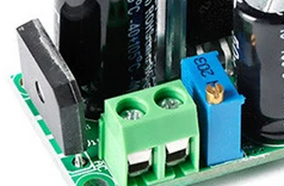
here's a better picture:
Ken from Peterborough
Hi Ron @zander & @ddistrbd1,
LM2596 (& LM2596HV) refer to integrated circuits which can be used to make buck regulator, probably originating from Texas Instruments, as they list a data sheet for it.
https://www.ti.com/product/LM2596
.. the term LM2596 does not define the circuit on a PCB .. it is reasonable to expect an LM2596 device on the PCB, but there could be many other things ...
"EC Buying" on AliExpress do list a product which can accept AC or DC
https://www.aliexpress.com/item/1005002604132980.html
And looking at their photo of the board, there is a 4 legged grey rectangular object at the left end that looks suspiciously like a bridge rectifier.
So while I make no claims to have examined this particular product,only the web page, the claim that it accepts AC seems plausible from what is visible in the photo.
If that is indeed a rectifier, then the module should be able to accept AC or DC, the downside for DC is that the redundant rectifier will add an extra voltage drop of around 1.4V, which will result in more heat dissipation and a higher minimum voltage required for operation.
Hope that explains the mystery.
Best wishes, Dave

