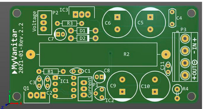
I received the mail order PCBs for my Miliohmmeter project and for a linear power supply control circuit.
For the Miliohmmeter the silk screen outlines a 1uF electrolytic capacitor. From the BOM, which lacked some specificity, I had incorrectly assumed a ceramic cap. I ordered the right part but am curious if, while I'm waiting, I would likely hurt anything if I tested with a temporary ceramic cap?
For the PSU control circuit one part is described on the BOM as: 1uF 50V multilayer 5mm pitch. The silk screen outline is a 4mm X 9mm rectangle with rounded ends. It's through hole. I can't find anything specifically known as a multilayer cap other than SMD ceramic caps. The silk screen shape suggests a polyester cap to me and is quite distinct from the outlines of the ceramic caps on the same board. Any ideas?
Hi @cecil,
Your trail of clues about the circuit is rather vague, so please understand the answers will correspongly be 'best guesses', and I might have answered differently if I had a more complete picture.
SMD ceramic caps are indeed usually multilayer for capacitances in the 1uF value range. Of course, 'multilayer' only means that the component has a repeated structure to cram a number of small components (in this case capacitors) together in a small space, rather like a single floor house design being stacked to form a block of flats. Providing the value (1uF) is the same, and the voltage rating is the same or greater than that specified for the electrolytic, I would normally expect it to be a good alternative.
Polyester capacitors have certain properties that make them suitable for certain tasks .. e.g. they typically have extremely low leakage ... but like all alternatives, they have their limitations as well. I don't know enough about the particular circuit to comment as to whether this position demands one.
Whilst the silkscreen image may be intending to suggest something, it might also be misleading ... as it is only an 'artistic' addition, it is feasible the PCB designer picked the 'nearest' footprint that would enable the part to be fixed to the board, knowing any deficiency in the silkscreen would not affect the circuit's operation.
Hope this helps a little ... sorry it is rather vague overall.
Best wishes, Dave
@davee Sorry to be so vague. My wife and I had switched laptops so she could listen to a library book her's wouldn't play, so I didn't have easy access to my files.
The link for the Miliohmmeter project is: https://www.pcbway.com/project/shareproject/Miliohmmeter_accurate_instrument_up_to10_mohms_8844aa44.html
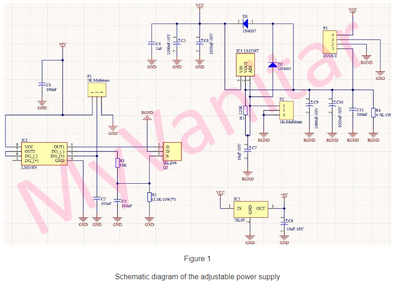
The pcb is illustrated there but you can barely make out C8, just above the terminals for the meter in the lower right corner. I've also attached the schematic from which I should have noticed the symbol for C8 was different from the ceramic caps, but I didn't.
A good depiction of the power supply control board is also atttached along with its schematic. The identity of C4 is my question. The schematic will open to legible size in a new tab. A full description of the project is at: https://www.pcbway.com/blog/technology/30V_4A_Adjustable_Power_Supply__CC_CV_.html
At the bottom of this blog post is the BOM with its less than satisfactory identification of component C4.
If you watch the video about the circuit, the designer seems specific by habit so I thought his silk screen markings were probably an accurate reflection of his intention. But I do wonder if he will deliver on this promise: "The theory behind how the combination IC1 and Q1 does the current limiting is a bit complex and it will be explained in a video in the future."
By the way I am seriously considering an ocilliscope purchase. I've identified a GW Instek GDS-1054B as capable enough and affordable if anyone wants to weigh in about such a choice.
My guess is, it's a multilayer ceramic capacitor (MLCC) like these:
https://www.vishay.com/docs/45171/kseries.pdf
You can find them for example at DigiKey, when filtering the Ceramic Capacitor category for Capacity 1uF, Voltage Rating 50V and Lead Spacing 0.197" (5.00mm)
Current projects:
- Modding my Gameboy Advance SP
- Turning Dalek into robot
Finished projects:
- Talking plant monitor (ESP8266)
- Mail box monitor (ESP8266-01S)
Other devices:
- Raspberry Pi 4B 4GB running Home Assistant
Hi @cecil,
I am not quite sure what is going on, but I think C4 may have changed identity between different versions of the power supply board. (The video shows an earlier version.)
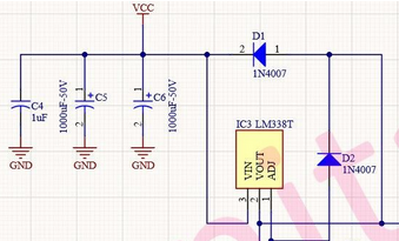
Anyway, assuming the board you are building matches this snip from the schematic:
Then a (MLCC) ceramic 1uF 30 (or more)V rating would probably be the best, although a electrolytic capacitor of the same specification would probably be equally good. Of course, if ordering a part, make sure it will be straightforward to physically solder into position.
...
As for the 'scope, I have only had a quick look at an advert on the web. It looked fine, although of course an advert tells you nothing about the 'real' quality of the device.
For most purposes in the past I have found a dual channel 'scope to be adequate, but traditionally scopes have always had a trigger input (including BNC socket etc.), with associated controls. It is often very useful to trigger off one signal, such as a rising edge at the input to a circuit, that you probably know what it looks like, then look for the effect in different parts of the circuit
.. I notice this 'scope, and others I considered a year or so ago, with four channels seem to rely on using 1 or or more of the channels as a trigger input.
A dual channel scope could be cheaper option if that would be helpful to you, but definitely make sure that it has 'proper' trigger input, in addition to the dual channel inputs.
Of course, you may have a good reason for 4 channels, and other aspects for choosing the GW Instek that I haven't considered. I am just sharing the aspects I looked for.
-----
Best wishes, Dave
MLCC it is. It seems so clear now.
I'm flying blind when I shop for an oscilliscope. I bought a used analog scope 15-20 years ago. It never worked and I probably still have it on a shelf somewhere. My neighbor works for Techtronics and he said my "bargain" was not worth fixing. I'll try to bone up on trigger inputs.
@davee Yes, the YouTube video is based on version one and the PCBs for sale are version two. C4 was added to the version two circuit. Thanks for your thoughts.


