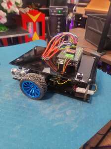
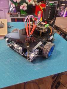
Jeffrey,
This sounds like a fun project. Are you teaching school age kids or adults? Will you be using ROS to implement the wall-following, maze-solving behaviors?
Good luck with the shield. Post some pictures when you can, I'd like to see what it looks like.
Tom
To err is human.
To really foul up, use a computer.
@thrandell I'll be happy to post some photos. The course will be geared towards all ages with beginners in mind. I won't be using ROS in this tutorial, but rather PID algoriths for wall following and maze solving as well as sensors for line tracking and so on using just an Arduino Mega. I'm hoping to include some odometry experiments using the wheel encoders as well. It's sort of a hands-on "build your own bot" thing.
Hey Jeffrey,
I thought of a problem I had with my 12 volt robot design that maybe I can help you avoid.
This robot has two decks and a circular bumper that is held up with piano wire so that it doesn’t touch the decks. When the bumper is hit it presses against a momentary switch. There are three switches and they are connected to a voltage divider so that when a switch or combination of switches is pressed a unique voltage gets applied to an ADC pin on the microcontroller.
My original design had the motors, 6 batteries, 12 volt regulator, and voltage divider on the lower deck and everything else on the upper deck. I wrote a simple test program that would drive the robot forward, avoid obstacles and escape from collisions. So I set it up, flipped the power switch and it lurched forward, did a hard stop, and then rolled forward slowly picking up speed?! My first reaction was WHAT! I didn’t program that…
To make a long story short, I discovered that when those 12V motors started they drew so much current that they induced a voltage in the voltage divider that the MCU interpreted as the bumper being hit from the back. When that happens the escape code stops the robot, pauses then starts slowly moving forward.
I tried adding small capacitors to the motors, braiding the 12V and GND wires, and re-routing the wires but finally settled on moving the voltage divider to the upper deck and routing the wires from the switches straight up through the upper deck to the divider. The best laid plans …
Anyway, I hope that story helps you avoid a similar problem.
Tom
To err is human.
To really foul up, use a computer.
@thrandell Here are a couple photos of the work in progress. I need to add the HC-05 module and do a bit more wiring on the shield for encoders and such but it's working pretty good. I've been playing around with the logic and PID for wall following, it's working out well. Of course tuning those things is half the fun!
JJ
Here are a couple photos of the work in progress.
Hi Jeffrey,
Nice looking robot. I like those wheels and the mounts for the ultrasonic sensors. How do you plan to use the Bluetooth HC-05?
I haven’t done much work with ultrasonic sensors so it’s good to know that they are working for your wall following. I know what you mean about tuning the controllers, the end result always seems like a compromise to me. I’ve used IR sensors for wall following and what worked great for one type of wall surface was a little wonky on another. Thanks for posting the photos!
Tom
To err is human.
To really foul up, use a computer.
@thrandell The HC-05 will be for manual control as well as picking the different programs that the robot can run on an app. I actually just finished a real-time radar display for the sensors that I'm pretty happy with so far. The US sensor method for the walls and mazes is great unless the sensor is at a certain angle to the wall, but I've programmed "countermeasures" into Beta to deal with unexpected situations and PID failures. Here's a video of Beta in action with a few different surface textures.
It's sort of a hands-on "build your own bot" thing.
I know this isn't exactly what you're planning to produce, but I thought you might find it interesting.
https://www.reddit.com/r/robotics/comments/10mnh39/are_there_studios_that_teach_robotics/
Tom
To err is human.
To really foul up, use a computer.
@thrandell Look for a 'Maker Club' in your area.
First computer 1959. Retired from my own computer company 2004.
Hardware - Expert in 1401, and 360, fairly knowledge in PC plus numerous MPU's and MCU's
Major Languages - Machine language, 360 Macro Assembler, Intel Assembler, PL/I and PL1, Pascal, Basic, C plus numerous job control and scripting languages.
Sure you can learn to be a programmer, it will take the same amount of time for me to learn to be a Doctor.


