I assume many of the readers here know about Philips HUE.
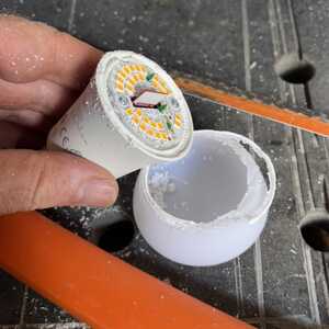
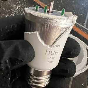
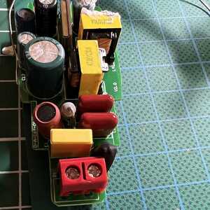
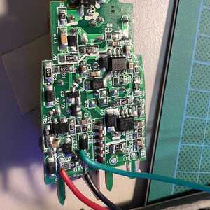
yesterday I decided to kill one of the cheaper Philips HUE lights so I could use it to turn ON and OFF the main lighting in my "lab" via a relay.
There are some tutorials on the internet, but sadly these are all older bulbs and I seem to be the first with this type.
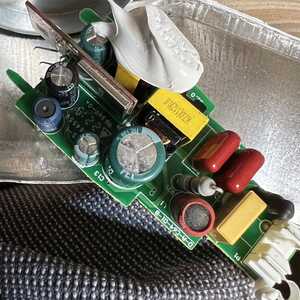
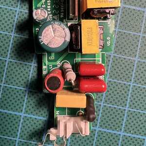
Have a look at the pictures to see what I did.
After some measuring and a bit of luck I found a 3.3V signal that can be controlled via the HUE app. The beauty of Philips HUE lamps is that they turn on and off very smoothly by fading in and out via PWM, and this is giving me problems.
The 3.3V signal is a PWM signal that I can't use on a relay. I could, but then relay won't have such a long life.
I tried solving this with using an OPAMP (LM358P) as a comparator (Thanks to the latest video of Bill), but I didn't get that working (yet?)
maybe a 555 timer can help?
or an RC filter.
I'm sure it's solvable with a micro-controller but I would love to get it working with just a few components.
Anyone has the golden tip for me?
@me-chiel Couple of quick thoughts. Instead of a relay, try a MOSFET. Also the board is likely an ESP, probably an ESP01 or similar. You are in Europe so lab lights are 240VAC and that is killing voltage so be careful.
Without knowing the complete setup it's hard to be more specific. Good luck!
EDIT: In 4th pic down, the board on edge is the WiFi board I think, I will bet it is an esp01.
First computer 1959. Retired from my own computer company 2004.
Hardware - Expert in 1401, and 360, fairly knowledge in PC plus numerous MPU's and MCU's
Major Languages - Machine language, 360 Macro Assembler, Intel Assembler, PL/I and PL1, Pascal, Basic, C plus numerous job control and scripting languages.
Sure you can learn to be a programmer, it will take the same amount of time for me to learn to be a Doctor.
@zander thanks for the feedback.
I don't think MOSFET's can switch 240VAC. And believe me, I'm careful.
The chip is not an ESP01. These can't use the Zigbee protocol only regular WiFi.
Hi @me-chiel,
I have never bought any of the 'smart' LED bulbs, so I can only guess what design decisions they have taken.
Also, I agree with personal safety concerns that Ron (@zander) has mentioned. Electronic units which are completely insulated often have the whole electronic board system directly connected to the mains power 'live' and 'neutral' lines. So please understand that any suggestions from this forum are entirely at your own risk.
-----------
Sorry, but personally, I do not understand what you are trying to achieve. Summarising your posting, I see:
I could use it to turn ON and OFF the main lighting in my "lab" via a relay.
The beauty of Philips HUE lamps is that they turn on and off very smoothly by fading in and out via PWM, and this is giving me problems.
The 3.3V signal is a PWM signal that I can't use on a relay. I could, but then relay won't have such a long life.
I don't think MOSFET's can switch 240VAC.
You say that the fading is giving you problems, but I don't understand what problems. What do you expect/hope that your final solution will look like?
---------------------
To achieve the dimming and colour changing effects, clearly it is necessary to vary the amount of light coming from each of (say) 3 different sets of LEDs, each set contributing a different colour. A separate PWM drive to each set is the most efficient way of achieving this dimming effect.
------------------
Of course, the 'slow fade effect' in which it changes brightness when commanded over a number of seconds will be achieved by gradually changing the mark-space ratio of the PWM, which is presumably part of the design of the control system/software ... it is not intrinsic to using PWM, which could change it's mark-space ratio in a single PWM cycle.
It is not clear if the 'slow fade' is implemented in the bulb control system, or the in the user software running on the tablet/phone/user control panel. Thus it is unclear if 'surgery/reprogramming' would be required to each bulb or if a 'user control' can be adapted or created to achieve a different aesthetic control.
--------------------
I don't know why a relay is identfied as part of your solution .. obviously a relay cannot be used for PWM of a light source?
------------
MOSFETs can control voltages well in excess of 240V, providing you pick an appropriate device.
Increasing the voltage that a FET can control typically increases the power needed to control it and the power loss within the device, so clearly a device designed to switch a few volts inside a mobile phone will not be selected for switching 300V and vice-versa, but devices switching up to at least 1200V are 'catalogue' parts, and much higher voltages are available for the more specialised requirements.
An individual FET might be seen as a 'DC' switch in many applications, but there are various circuit designs to enable them to switch 'AC'.
--------
Best wishes, Dave
Hello Davee, let me try to rephrase some stuff.
You say that the fading is giving you problems, but I don't understand what problems. What do you expect/hope that your final solution will look like?
I try to operate a 230VAV device. By turning it ON or OFF. let's make it a power outlet to keep things simple.
It is not clear if the 'slow fade' is implemented in the bulb control system, or the in the user software running on the tablet/phone/user control panel. Thus it is unclear if 'surgery/reprogramming' would be required to each bulb or if a 'user control' can be adapted or created to achieve a different aesthetic control.
The slow fade-in & out as you can see in the video is implemented in the bulb control system.
One can turn on the lights by using their original light-switch. The LED lamp will then fade in (or out if you turn the switch off)
I don't know why a relay is identfied as part of your solution .. obviously a relay cannot be used for PWM of a light source?
You're absolutely right about that:)
I'm looking for a way to "ignore"/"change" the startup-fade-in (and probably later the end-fade-out) sequence, so I can use that signal to turn a Relay on or off.
If the signal from the "hacked" PCB was a simple 3.3V for on or 0V for OFF I would be done. Sadly this isn't the case.
I hope I made things more clear for you.
Hi @me-chiel
most probably you need an extra 5V power source to drive the schmitt trigger and the relay. I don't think it can be done with only 3.3V.
Get to know the frequency of the 3.3V PWM signal
Calculate an RC circuit which will reach the trigger level at, let's say, half of PWM signal's duty cycle
Use an 74HC14 (or similar) CMOS inverting Schmitt Trigger and an BC557 (or similar) PNP Transistor to drive the relay - hysteresis of 74HC14 is big enough to avoid flickering output
The best option is to simulate and fine tune the real behaviour in LTSpice
As already mentioned by @davee and @zander - be very careful with high voltages involved!
Good luck!
Rule of Thumb in hardware/software engineering:
From the estimated time to complete a project you need:
5% for the engineering itself
95% securing everything against any strange idea users can have
and the remaining
150% for finding and fixing bugs that you thought never could happen
@hzulu thanks for this answer. I have to dive in LTspice, but your idea sounds like a plan. I did find a 5V output on the PCB. (next to 400V and 600V so I promise to be very careful)
I will measure the PWM signal and check if it's 100KHz as stated in some forums to do some RC calculation.
Thanks again for the tip & your time to sketch a schematic!
If I find the solution I will gladly leave it here.
@me-chiel What I meant by MOSFET is to have the MCU control the MOSFET that drives the DC coil of the relay to close the 240VAC contacts.
My guess was that the vertical board appears to have a typical WiFi 'can' on it and I know esp's are widely used for IOT devices.
I don't have the hardware or enough interest, so I will bow out. Good luck!
First computer 1959. Retired from my own computer company 2004.
Hardware - Expert in 1401, and 360, fairly knowledge in PC plus numerous MPU's and MCU's
Major Languages - Machine language, 360 Macro Assembler, Intel Assembler, PL/I and PL1, Pascal, Basic, C plus numerous job control and scripting languages.
Sure you can learn to be a programmer, it will take the same amount of time for me to learn to be a Doctor.
Hi @me-chiel,
Thanks for your clarification of your aims, but unfortunately I am still somewhat mystified about them. Apologies if the following seems a little patronising .. that is not my intent, but I do think it is important for everyone to be clear about your aims if they are to help you and asking enough questions to achieve without sounding patronising can be very difficult.
---
You started with the Philips 'smart LED' bulbs, which according to your update have a built-in slow fade characteristic. However, it seems you don't like this slow fade characteristic. If this is part of the intrinsic bulb's design, then are you contemplating some kind of surgery (software and/or hardware) on all of your bulbs, or maybe you have some alternative bulbs in mind?
-------------
Surely the simplest answer to this is to use 'non smart LED bulbs'? They are much cheaper anyway.
Perhaps you wish to retain the colour changing aspect of the Philips bulb? Obviously, this adds a level of complexity to the situation, as the simplest LED 'bulb's are a fixed 'colour'.
Perhaps you could clarify your aims in this respect?
------------
All of my lighting circuits have traditional light switches on the walls, which are obviously trivial from the technology viewpoint, but require wires between the switches and the light fittings, which can be very inconvenient to fit. So am I right in guessing you are looking for a wireless solution to control the lights?
You may wish to explain your wishes.
--------
If this is the case, surely there are almost countless devices on the market which can switch power using either a dedicated switch, remote control unit or phone/tablet.
As I haven't actually bought any of them, I am clearly not the best person to make any specific recommendations, but a quick glance at Banggood showed a number of approaches, with small remote modules to control an arbitrary mains powered load, most being much cheaper than a single ''smart LED bulb'.
This is not a recommendation (for device or supplier), but (assuming it achieves the advert claims), is just a suggestion for you to comment on whether it is a useful approach to you, and if not, how your aim dffers from the advert's claims.
--------
Of course, you might be wishing to replicate the commercial modules for some reason, perhaps to add some capability, although if the prices I spotted are a guide, it may be difficult to find a cheaper solution. Again, your comments could help.
--------
I am sorry this message is about asking more questions, not providing answers, but I hope it helps in your overall project flow.
Best wishes, Dave

