Hello all,
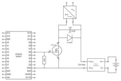
I'm fairly new to all of this and I tried to build a circuit to control the brightness of an EL Panel with one of the PWM pins of an Arduino Nano.
It actually dims, but there are some issues.
The PWM has a range from 0 to 255.
- at 0, the EL Panel is completely off (that would be fine)
- starting with 1, it is already too bright
(When I connect the inverter directly to the buck converter and change it's output, I can set the brightness way lower) - between around 20 and 230 it flickers
According to the data sheet, the inverter driving the EL Panel has
- Input voltage: 12V DC
- Output voltage: 110V AC
- Frequency: 1000Hz
- Max. current: 300mA
Can you please help me using the full range of brightness and get rid of the flicker?
Thank you, kopi
@kopi Just a casual observation. Different MOSFETS (if that is what you are controlling) have different outputs relative to the input so a very simplistic solution is to change the MOSFET to one that has a more linear response.
I would also suspect the inverter has a response curve, but you seem to say it does not so that should not be a problem.
I hope my response has been helpful in some small way.
First computer 1959. Retired from my own computer company 2004.
Hardware - Expert in 1401, and 360, fairly knowledge in PC plus numerous MPU's and MCU's
Major Languages - Machine language, 360 Macro Assembler, Intel Assembler, PL/I and PL1, Pascal, Basic, C plus numerous job control and scripting languages.
Sure you can learn to be a programmer, it will take the same amount of time for me to learn to be a Doctor.
@kopi
Not sure why either of your problems is happening. I don't use PWM very often but I'm wondering if the flickering is caused by your inverter running at 1KHz and the Arduino's PWM running at 980Hz. Perhaps they're interfering with each other's timing.
Also, I don't think you need the 10K resistor on the MOSFET gate. Its purpose is to drag the gate low to make sure that it shuts off promptly when the gate voltage is released.Since you're driving the gate all the time via the NANO pin I don't think you need to tie the gate low via that resistor.
Here's an article to read more on the PWM frequency ...
Anything seems possible when you don't know what you're talking about.
Hi @kopi (& @will and Ron @zander),
I haven't played with EL panels, and unfortunately you haven't provided any references to data sheets for the inverter or the battery/buck converter, so there is a lot left to the imagination.
The 10k resistor may not do much, but at worst it is harmless, and it might help ensure the gate is switched off if the Nano is powered down whilst the battery/buck is powered, so I don't have any concerns about that.
The FET could really do with a higher gate voltage drive, though assuming it is a 5V 'original' Nano, it might just be enough.
If you are using a low PWM frequency, say in the 100s of Hz range, that could certainly be a problem. That might be fixable in software. A quick Google suggested higher requency options are possible, but I didn't read it properly.
... I presume the chopped output from the FET needs to be converted to a DC value for the input to inverter ... so the 47 uf capacitor could be struggling, when combined with low frequncy chopping. I assume you are not expecting the inverter to be switching on and off at the PWM rate. However, as I don't know what current demand from the inverter is (no data, other than "Max current =300mA"), I am left with more uncertainities than facts.
----------
As Will says, if the inverter frequency is near the chopping frequency, that is suggesting even more possibilities of producing a mixing of the frequencies.
-----------
Generally I would look for much higher chopping frequency and probably larger value capacitor at input of inverter, aiming to get a 'smooth' DC but lack of visibility of the system makes me very uncomfortable about recommending it ...
------
However, this 'analysis' makes the whole system design look a bit crazy, as you have a buck regulator, appearing to feeding a sort of 'poor mans' buck regulator (that doesn't have an inductor) made from the Nano, Fet and 47uF capacitor, feeding a boost converter. i.e. three voltage converters in a row. I am not saying it can't be made to work, but I would hope there is a better feasible solution.
Is this scheme recommended by the EL manufacturer? It feels like there is at least one 'regulator' too many. But as I said at the start, I have never worked with EL panels...so I might be just confused.
Best wishes, Dave

