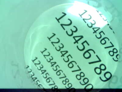
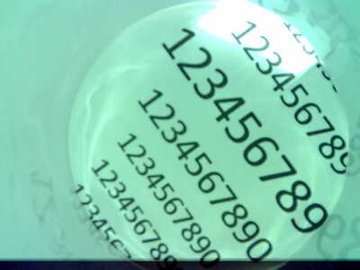
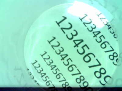
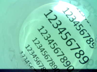
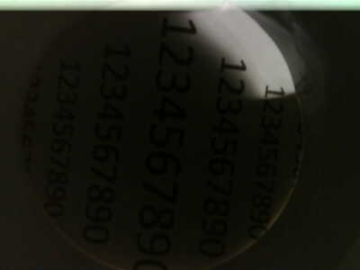
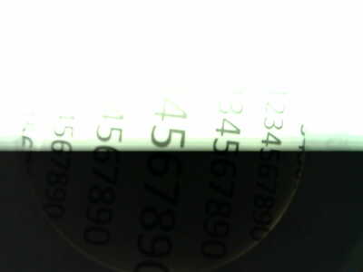
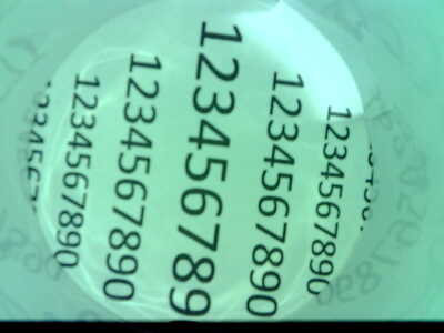
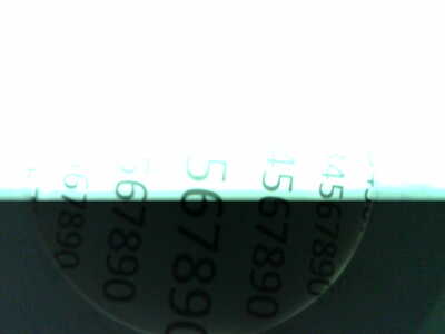
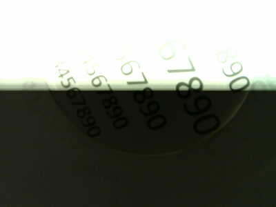
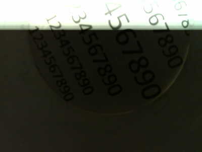
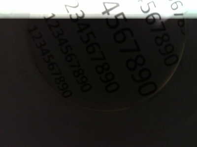
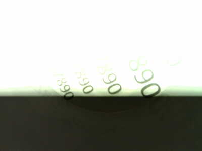
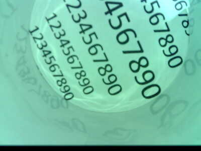
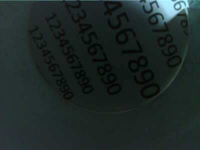
@stefandws At the risk of looking foolish, just modify the sketch that produces the picture you like with the extra code to do the time lapse. I looked briefly at both sketches and the picture quality should be identical. Something doesn't make sense.
First computer 1959. Retired from my own computer company 2004.
Hardware - Expert in 1401, and 360, fairly knowledge in PC plus numerous MPU's and MCU's
Major Languages - Machine language, 360 Macro Assembler, Intel Assembler, PL/I and PL1, Pascal, Basic, C plus numerous job control and scripting languages.
Sure you can learn to be a programmer, it will take the same amount of time for me to learn to be a Doctor.
Hello Ron,
thank you for your reply!
For me it does not make any sense too. The only difference for my understanding happens within the "loop"
I am wondering what is the difference in triggerimng the camera by pressing the hardware bottom compared to triggering the camera within the loop. There must be some sort of difference I do not understand.
Is there some kind of reset required within the loop?
the difference in the code:
@stefandws Yes, very strange. What I will try to do today is set up two of my cameras and try both sketches. IF it fails like yours, then I will convert the 'reset' version to a millis() based timed shooter. only because I can't think of any other test to do. They are identical in the code that matters.
First computer 1959. Retired from my own computer company 2004.
Hardware - Expert in 1401, and 360, fairly knowledge in PC plus numerous MPU's and MCU's
Major Languages - Machine language, 360 Macro Assembler, Intel Assembler, PL/I and PL1, Pascal, Basic, C plus numerous job control and scripting languages.
Sure you can learn to be a programmer, it will take the same amount of time for me to learn to be a Doctor.
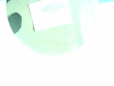
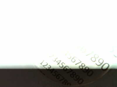
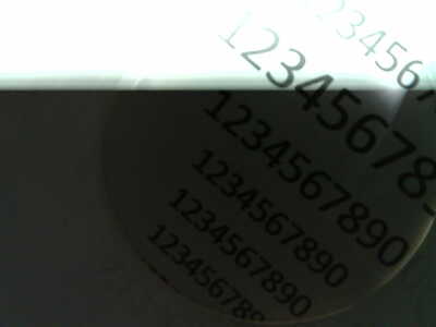
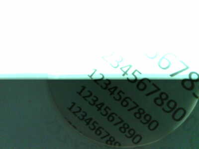
@stefandws I think I know what is happening. It's just glare that is messing up the pictures.
The camera has to be physically aligned exactly the same for both tests. The best way to do this is to mechanically secure the camera and ONLY use your PC to change sketches and reset if needed. IF you move the camera even a nanometer it will change the result. If that is too difficult for you to do, just aim the camera at the outdoors and run both sketches.
First computer 1959. Retired from my own computer company 2004.
Hardware - Expert in 1401, and 360, fairly knowledge in PC plus numerous MPU's and MCU's
Major Languages - Machine language, 360 Macro Assembler, Intel Assembler, PL/I and PL1, Pascal, Basic, C plus numerous job control and scripting languages.
Sure you can learn to be a programmer, it will take the same amount of time for me to learn to be a Doctor.
@stefandws If taking pictures of your water meter is the project, then look into the arducam line of products. Much more expensive but also much better cameras. I would look into the PICO and the Pi ZERO as alternatives. Both are available in wireless models. The PICOW is very available while the Pi ZERO is still in short supply. I also have a use for a remote camera and was going to use a Pi ZERO but have found a PICOW solution that is easier to source.
Hello Ron,
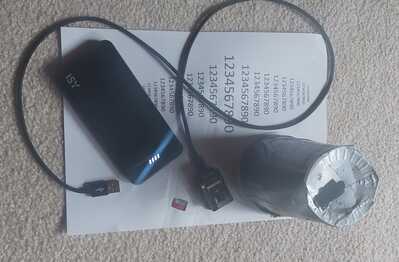
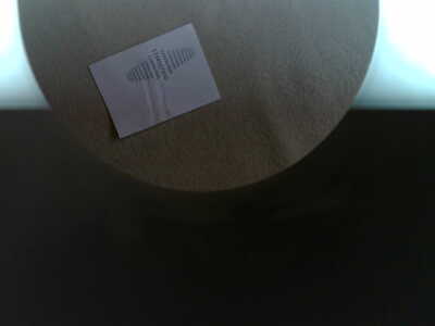
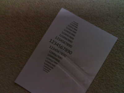
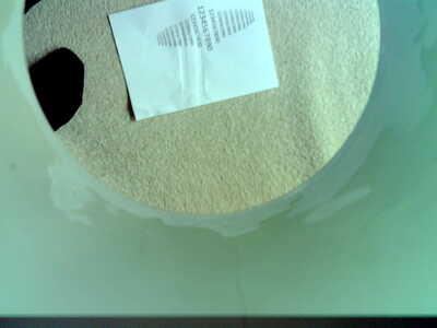
glare can be excluded as reason for generating scrap pictures since the mechanical setup is exactly same. This time Camera fixed by cable ties "solid" onto the yogurt cup building the housing for the test setup. Camera position ist not changed on the housing when SD-Card is changed.
I cannot attach new pictures since I get the message "No more attachments are allowed today" to explain the results of the next test ... I guess I have to wait until tomorrow.
ESP32 CAM Camera with MicroSD storage
esp32cam-microsd.ino
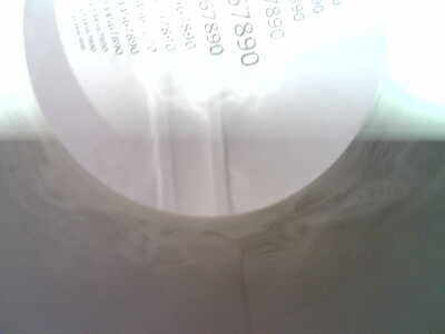
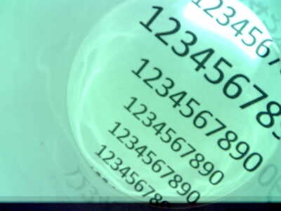
all the pictures triggered by the button are perfect ... manual triggering every 10sec or even faster
ESP32-CAM Time-lapse camera
esp32cam-timelapse.ino
a)
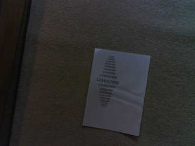
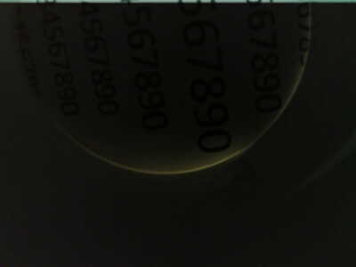
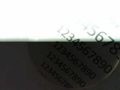
by pressing rst-button right after connecting the power supply the frst picture triggered by the "loop-code" is as good as the result of the "non-loop-code" ... all other pictures 2,3... automatically taken after 10sec are complete scrap.
b)
starting the loop script without pressing rst-button after connecting to power supply --> all the pictures triggered every 10sec are scrap.
I will order a new device ... maybe hardware failure?
@stefandws If you are sure the camera doesn't move then it may be brownout. Try commenting out the statement or better still change the 0 to a 1
// Disable brownout detectorWRITE_PERI_REG(RTC_CNTL_BROWN_OUT_REG, 0);
then watch the serial output for a brownout message. If you get one, then you need to use a better power source or better cable.
The reset sketch will not be affected but the time lapse will. Change the time lapse delay longer until the brownout goes away. Also use a really high quality power source with 5V at 5A. This means after uploading the sketch, disconnect the USB cable from the PC and plug it into a more powerful 5V supply.
If I wasn't so ill I would do all this, but I am too weak now to do much.
First computer 1959. Retired from my own computer company 2004.
Hardware - Expert in 1401, and 360, fairly knowledge in PC plus numerous MPU's and MCU's
Major Languages - Machine language, 360 Macro Assembler, Intel Assembler, PL/I and PL1, Pascal, Basic, C plus numerous job control and scripting languages.
Sure you can learn to be a programmer, it will take the same amount of time for me to learn to be a Doctor.
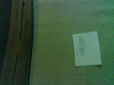
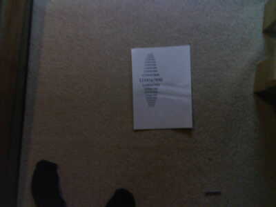
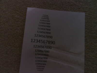
@stefandws What I see in your provided pictures is part of the picture is ok, and part is not. This indicates to me that the camera moved. Either the camera moved when extracting the TF card or your board requires you to hold the BOOT button. As I think I told you before, point the camera at the ceiling, or outdoors and then compare. Forget for now taking a picture of the water meter, that is a separate problem to be solved.
First computer 1959. Retired from my own computer company 2004.
Hardware - Expert in 1401, and 360, fairly knowledge in PC plus numerous MPU's and MCU's
Major Languages - Machine language, 360 Macro Assembler, Intel Assembler, PL/I and PL1, Pascal, Basic, C plus numerous job control and scripting languages.
Sure you can learn to be a programmer, it will take the same amount of time for me to learn to be a Doctor.
Hi @stefandws,
Ron (@zander) knows a lot more about this than I do, so this is only a random suggestion to consider. (Ron, sorry to see that your illness is adversely affecting you at the moment --- I wish you all the best for a quick recovery.)
Just looking at the photos, I wondered if the onboard white LED (or any other light source for that matter) is making a major contribution to the illumination? Could there be a problem with the timing of the LED being illuminated with the time-lapse pictures, so that the pictures are being taken in the dark some of the time ... or maybe the light level is changing so that it can massively under- and over-expose? I know the phone cameras do lots of 'auto-adjustments' to try to get the best picture, effectively analysing one frame to try to get a better picture on the next frame, and I suspect at least some primitive types of auto-adjustment are active here.
(I am also unclear if this is internal to the camera module or is part of the C code runnning on the ESP32 - remember the library files include a considerable amount of extra code to the code in your main program, which may include some 'magical' benefits.)
Sorry, I haven't looked at the code, so I am unclear if the LED is being controlled. A possible test might involve providing a separate 'constant and adequate' light source, to see if it improves the situation. This may not be the solution you are looking for, but might give some clues as to what is happening -- or it might be a red herring!
Best wishes,
Dave
@davee FYI @stefandws Dave I don't see any code to turn on the LED. I did a file compare as did Stefan and the camera code is identical. What I would like to see is just lay the camera on the table beside the PC and take a random picture then use the other sketch. I doubt there will be a difference, but there might be a power issue and I gave him instructions on how to deal with that. In the 'not good' pictures, I can actually see a good image in some sections which is why he needs to test just shooting at the ceiling. At this point I feel my time is better spent elsewhere, the code is identical and I have suggested several debugging steps that the OP has so far not followed. Until I see both those steps done I will wait. If he has forgotten, step 1 is to enable the brownout detector and step 2 is shoot the ceiling or out a window.
First computer 1959. Retired from my own computer company 2004.
Hardware - Expert in 1401, and 360, fairly knowledge in PC plus numerous MPU's and MCU's
Major Languages - Machine language, 360 Macro Assembler, Intel Assembler, PL/I and PL1, Pascal, Basic, C plus numerous job control and scripting languages.
Sure you can learn to be a programmer, it will take the same amount of time for me to learn to be a Doctor.
Thank you for your efforts trying to help!
back to scratch:
- original "loop" code
( ESP32-CAM Time-lapse camera, esp32cam-timelapse.ino,Takes time-lapse pictures with ESP32-CAM Saves images to MicroSD Card,DroneBot Workshop 2022, https://dronebotworkshop.com
delayTime = 10000
camera without yogurt cup housing (distance starting from approx 1m getting closer up to yogurt cup distance) - original "loop" code, camera fixed within yogurt cup housing ... (distance starting from approx 1m getting closer up to yogurt cup distance)
- modified code ... parameters et to ... eg aec_value set to 1200,....
camera without yogurt cup housing (distance starting from approx 1m getting closer up to yogurt cup distance) - modified code ... parameters et to ... eg aec_value set to 1200,....'
camera fixed within yogurt cup housing ... (distance starting from approx 1m getting closer up to yogurt cup distance) - modified code (loop) ... parameters et to ... eg aec_value set to 1200,....'
camera fixed within yogurt cup housing ... final yogurt cup distance ... first picture triggered by rst-button - sample-code without loop ... fixed within yogurt cup housing
Take picture when button pressed
Store image on MicroSD card
modified camera settings
modified code camera settings
// Camera quality adjustments
sensor_t * s = esp_camera_sensor_get();

// BRIGHTNESS (-2 to 2)
s->set_brightness(s, 2);

// CONTRAST (-2 to 2)
s->set_contrast(s, 0);

// SATURATION (-2 to 2)
s->set_saturation(s, 0);

// SPECIAL EFFECTS (0 - No Effect, 1 - Negative, 2 - Grayscale, 3 - Red Tint, 4 - Green Tint, 5 - Blue Tint, 6 - Sepia)
s->set_special_effect(s, 0);

// WHITE BALANCE (0 = Disable , 1 = Enable)
s->set_whitebal(s, 1);

// AWB GAIN (0 = Disable , 1 = Enable)
s->set_awb_gain(s, 1);

// WB MODES (0 - Auto, 1 - Sunny, 2 - Cloudy, 3 - Office, 4 - Home)
s->set_wb_mode(s, 0);

// EXPOSURE CONTROLS (0 = Disable , 1 = Enable)
s->set_exposure_ctrl(s, 0); // 1

// AEC2 (0 = Disable , 1 = Enable)
s->set_aec2(s, 0);

// AE LEVELS (-2 to 2)
s->set_ae_level(s, 1);

// AEC VALUES (0 to 1200)
s->set_aec_value(s, 1200);


// GAIN CONTROLS (0 = Disable , 1 = Enable)
s->set_gain_ctrl(s, 1);

// AGC GAIN (0 to 30)
s->set_agc_gain(s, 15);


// GAIN CEILING (0 to 6)
s->set_gainceiling(s, (gainceiling_t)0);


// BPC (0 = Disable , 1 = Enable)
s->set_bpc(s, 0);

// WPC (0 = Disable , 1 = Enable)
s->set_wpc(s, 1);

// RAW GMA (0 = Disable , 1 = Enable)
s->set_raw_gma(s, 1);

// LENC (0 = Disable , 1 = Enable)
s->set_lenc(s, 1);

// HORIZ MIRROR (0 = Disable , 1 = Enable)
s->set_hmirror(s, 0);

// VERT FLIP (0 = Disable , 1 = Enable)
s->set_vflip(s, 0);

// DCW (0 = Disable , 1 = Enable)
s->set_dcw(s, 1);

// COLOR BAR PATTERN (0 = Disable , 1 = Enable)
s->set_colorbar(s, 0);
Test setup ... energy supplied by fully charged power bank 10.000mAh
Results:
1) original "loop" code without yogurt cup housing
(distance starting from approx 1m getting closer up to yogurt cup distance)
2) original "loop" code - camera fixed within yogurt cup housing
3) modified code without yogurt cup housing
4) modified code - camera fixed within yogurt cup housing
first picture by pressing hardware rst button
second pictures triggered by loop ... distance approx 1m
closer almost final position
final poasition:
still final position without touching anything
@stefandws I am trying to help and asked you to do two things. You have done neither, goodbye.
First computer 1959. Retired from my own computer company 2004.
Hardware - Expert in 1401, and 360, fairly knowledge in PC plus numerous MPU's and MCU's
Major Languages - Machine language, 360 Macro Assembler, Intel Assembler, PL/I and PL1, Pascal, Basic, C plus numerous job control and scripting languages.
Sure you can learn to be a programmer, it will take the same amount of time for me to learn to be a Doctor.
@stefandws If you are sure the camera doesn't move then it may be brownout. Try commenting out the statement or better still change the 0 to a 1
// Disable brownout detectorWRITE_PERI_REG(RTC_CNTL_BROWN_OUT_REG, 0);then watch the serial output for a brownout message. If you get one, then you need to use a better power source or better cable.
1) BROWN_OUT 1
void setup() {
// Disable brownout detector
WRITE_PERI_REG(RTC_CNTL_BROWN_OUT_REG, 1);
rst:0x1 (POWERON_RESET),boot:0x13 (SPI_FAST_FLASH_BOOT)
configsip: 0, SPIWP:0xee
clk_drv:0x00,q_drv:0x00,d_drv:0x00,cs0_drv:0x00,hd_drv:0x00,wp_drv:0x00
mode:DIO, clock div:1
load:0x3fff0030,len:1344
load:0x40078000,len:13836
load:0x40080400,len:3608
entry 0x400805f0
Initializing the camera module...Camera OK!
Initializing the MicroSD card module... Mounting MicroSD Card
Delay Time = 10000 ms
Picture file name: /image0.jpg
Saved file to path: /image0.jpg
Picture file name: /image1.jpg
Saved file to path: /image1.jpg
Picture file name: /image2.jpg
Saved file to path: /image2.jpg
Picture file name: /image3.jpg
Saved file to path: /image3.jpg
Picture file name: /image4.jpg
Saved file to path: /image4.jpg
2) BROWN_OUT 0
void setup() {
// Disable brownout detector
WRITE_PERI_REG(RTC_CNTL_BROWN_OUT_REG, 0);
ets Jul 29 2019 12:21:46
rst:0x1 (POWERON_RESET),boot:0x13 (SPI_FAST_FLASH_BOOT)
configsip: 0, SPIWP:0xee
clk_drv:0x00,q_drv:0x00,d_drv:0x00,cs0_drv:0x00,hd_drv:0x00,wp_drv:0x00
mode:DIO, clock div:1
load:0x3fff0030,len:1344
load:0x40078000,len:13836
load:0x40080400,len:3608
entry 0x400805f0
Initializing the camera module...Camera OK!
Initializing the MicroSD card module... Mounting MicroSD Card
Delay Time = 10000 ms
Picture file name: /image0.jpg
Saved file to path: /image0.jpg
Picture file name: /image1.jpg
Saved file to path: /image1.jpg
Picture file name: /image2.jpg
Saved file to path: /image2.jpg
Picture file name: /image3.jpg
Saved file to path: /image3.jpg
Picture file name: /image4.jpg
Saved file to path: /image4.jpg
Picture file name: /image5.jpg
Saved file to path: /image5.jpg
Picture file name: /image6.jpg
Saved file to path: /image6.jpg
I can't see any difference in the serial monitor output concerning "brown out" ... in case there should be a difference to be noticed.
==> always the first picture triggered by hardware rst-button is perfect ... each picture triggered within the loop is of no use
the test setup ist not being touched except triggering rst-button at start .. the camera is definitely not being moved in between triggering by rst and within the loop!
must be some setting issue which is behaving different by triggering by rst button compared to triggering camera within the loop ... at least for my understanding.

