Hi Folks,
In the introduction session for the ESP32 Cam (Getting started with the ESP32 Cam) Bill says on Minute 4:36 regarding to the power supply: "You need to use the one (3.3 Volt pin) or the other (5V Pin), but not both" of the ESP32 Cam
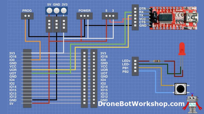
I build the ESP32 Developers Modul and the power supply base. When I powered up the developer module over the dupont connnection, I measured 3.3.Volt and 5 Volts on the corresponding pins . That means, when I will hook up the camera modul it will be powered by 3.3 and 5 V at the same time. Is it posible to do this or do I have an error in my thinking? I still not have tested the camera modul with the base, because i'm afraid to destroy the ESP 32 Cam.
The ESP32 chip itself runs on 3.3V. For convenience, the board has an AM1117 regulator that will bring a 5V power line down to 3.3V. The 3.3V pin looks like it is directly connected to the output of that regulator, so if you power the board with a 5V line, you should expect to see 3.3V on that pin.
What Bill was talking about in the video is that you do not want to connect a 5V supply and a 3.3V supply at the same time to the respective pins. If you do that, the AM1117 will end up fighting with your 3.3V power supply.
"A resistor makes a lightbulb and a capacitor makes an explosion when connected wrong"
"There are two types of electrical engineers, those intentionally making antennas and those accidentally doing so."
Hi, @jker, Thats exactly what I mean, when I power up the module through the Power supply base, I connect the 3.3V and the 5 V to the ESP Cam. There is no switch or jumper I could use to power it only with one of them
Hmm... I hadn't looked at that video in detail. I agree there is a contradiction here between the two videos.
Your onboard AM1117 _is_ going to be fighting with your 3.3 supply, but fortunately it shouldn't hurt anything if you're also using a regulator for the 3.3V supply. Both are going to try to maintain the line at 3.3V, one of them is going to have a slightly higher threshold.
Effectively what happens here is very similar to using two voltage regulators in parallel. Usually the vast majority of the current will be drawn from one regulator, whichever has the slightly higher voltage threshold, with the other rather underutilized. This is only really a problem if you are drawing more current than one regulator can handle, which is far from the case here.
"A resistor makes a lightbulb and a capacitor makes an explosion when connected wrong"
"There are two types of electrical engineers, those intentionally making antennas and those accidentally doing so."
Thanks a lot, @jker, that helps. I can leave the design as it is and go on testing the module.
I'm actually a little bit more concerned about running the FTDI programmer in 5V mode for programming a chip that runs on 3.3V logic. But I haven't looked into this in detail.
"A resistor makes a lightbulb and a capacitor makes an explosion when connected wrong"
"There are two types of electrical engineers, those intentionally making antennas and those accidentally doing so."

