A short answer is that schematic representations of components often do not represent the actual foot print of the physical device.
As in this example, most of the inputs are on the left of the diagram, the outputs on the right, power on top, and grounds on the bottom.
Hope that helps.
SteveG
@kabl I doubt it is anything but convenience, putting 4 wires on each side makes for a more crowded diagram. Logically it makes no difference.
First computer 1959. Retired from my own computer company 2004.
Hardware - Expert in 1401, and 360, fairly knowledge in PC plus numerous MPU's and MCU's
Major Languages - Machine language, 360 Macro Assembler, Intel Assembler, PL/I and PL1, Pascal, Basic, C plus numerous job control and scripting languages.
Sure you can learn to be a programmer, it will take the same amount of time for me to learn to be a Doctor.
I followed the guide at https://www.electronics-tutorials.ws/waveforms/555_oscillator.html (scroll down to the section "Improved 555 Oscillator duty cycle) to invert the signal from the 555, and I got the duty cycle well below 50%. Yay! Happy!
Using the calculator at https://mechatrofice.com/calculator/555-multivibrator I got R1=51k resistor, R2=1M resistor and a 47 mikrofarad capacitor to get 1.6 seconds high and 35 seconds low. A 0.01 mikrofarad capacitor is connected between PIN5 and ground. I am using a 9 volt battery to run it.
Using these values, the LED is now lit for approximately 1.6 seconds, but is idle only for approximately 9-10 seconds.
What am I missing here? This seems to be larger than the effect of tolerance/value range.
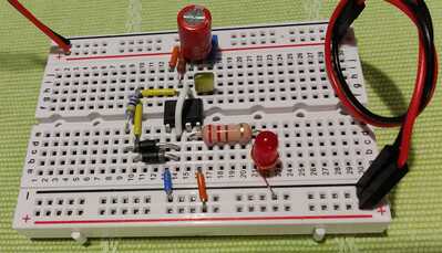
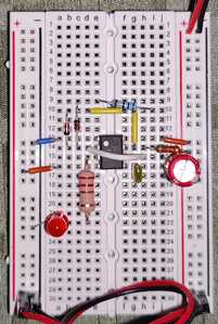
This is my current setup. I use small jump leads and not jumpwires as I think it easier to trace and to get an overview. Feedback, tips and harsh words are all equally welcome, so I can improve my skills and knowledge 🙂
Hi @kabl,
Good to actually be able to see your circuit!
I don't have an easy answer, and I am probably missing the obvious, but my first suspicion is the diodes ... or more precisely D1, connected between pins 2 and 7 of the 555.
What type are they? (I don't recognise the numbers I can actually see - I fear they may be power rectifiers or something else, which are optimised for forward conduction, in exchange for tolerating a tiny reverse current. )
Or maybe D1 is faulty?
------
My thinking is your timing suggests the 'effective' value of R2 appears to be around 300 kOhms, not 1 M (or 1.2M from the colour coding). It is possible R2 is itself faulty, but falling in value would be unusual ... but if D1 is conducting a small current when reverse biased, this would have a similar effect to R2 being lower in value.
Please note that having a resistor as high as 1 MOhm means currents of just a few microAmps will 'wreck' the simple RC time calculation predictions, and leakage currents of this level are not unusal in diodes, so you on the 'edge' with the values chosen, and D1's characteristics in particular are critical.
I would advise starting with D1 and D2 to be small signal diodes, like 1N914 or 1N4148 ...and even these may depend on which manufacturer made them, etc.
Best wishes, Dave
@davee Thank you so much for your reply. I have some of these 1N4148, I will try these after work today. I have to go thru my mail when I get back from work and find the details on the diode I have mounted now, I think it is a 1N4007.
Well spotted on the resistor - I played around with 1MOhm, 1.2MOhm and 1.5MOhm.
Hi @kabl,
Good luck with your trial.
Bear in mind, electrolytic capacitors typically have a much wider capacitance value tolerance band, (e.g. several 10s of %), than (say) resistors, or even non-electrolytic capacitors. Furthermore, the value can vary widely with operating conditions, such as age, dc voltage applied and temperature - hence, they are generally best avoided for applications where the operation of the circuit depends upon the exact value ... which includes many timing operations.
However, I would expect the capacitor value uncertainity to affect both on and off time periods, so I don't think it is responsible for the major part of the discrepancy you have observed.
Electrolytics are better suited to applications where having a 'bit too much capacitance' has little or no effect, and then the usual practice for reliable operation is to fit a 'larger than needed' value. Sadly, larger values also implies physically larger and higher cost, so you will encounter cases with commercial circuits in which drivers other than reliable operation, typically cost, take precedence.
Best wishes, Dave.
@davee Thank you so much for your reply. I have some of these 1N4148, I will try these after work today. I have to go thru my mail when I get back from work and find the details on the diode I have mounted now, I think it is a 1N4007.
Well spotted on the resistor - I played around with 1MOhm, 1.2MOhm and 1.5MOhm.
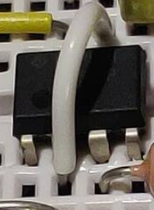
Hi@kabl, As I'm looking at your circuit, I think I see a potential problem-- there is no connection from pin 6 to pin 2 on your circuit layout that I can discern.. please e-check your circuit wiring so see if it is correct.. let us know what you find..
regards,
LouisR
LouisR
Hi @inst-tech,
re: there is no connection from pin 6 to pin 2 on your circuit layout that I can discern
Isn't this white wire was performing that task?
Best wishes, Dave
@davee; you were spot on about the diodes. I removed the ones I had in the previous setup and put in 1N4148 instead. Now it works like a charm 🙂 See picture for updated setup and video for demonstration.
Rewired and working;
Live demonstration, 1 minute.
Thank you so much to everyone for all your help, I have learned a great deal from this. Looking forward to continue tinkering and playing with electronics 🙂
Continuing this project, what would be the best way to handle a higher current? The radio I intend to use draws about 900 milliamperes, a lot more than the 555 can handle. Electromechanical relays are not an option.
Can it be done another way?
@kabl Mosfet?
First computer 1959. Retired from my own computer company 2004.
Hardware - Expert in 1401, and 360, fairly knowledge in PC plus numerous MPU's and MCU's
Major Languages - Machine language, 360 Macro Assembler, Intel Assembler, PL/I and PL1, Pascal, Basic, C plus numerous job control and scripting languages.
Sure you can learn to be a programmer, it will take the same amount of time for me to learn to be a Doctor.
@zander ; thank you!
Looking into that, it seems they have different forward diode voltage. As I understand it, this means how much the voltage will drop over the mosfet. This is a 3 volt logic, and looking at the TSM4NB60CI it has a forward diode voltage of 1.13 volts.
For arguments sake, lets say the 3 volt logic needs 3 volts to trigger. I know it requires between 2.75-3.25 volts, but lets run with 3 volts just to make it easier. Does that mean that the voltage in has to be 3+1.13 volts to trigger it, to compensate for the drop over the mosfet?
Kind regards,
Knut


