@will Why, and what part number as an example?
First computer 1959. Retired from my own computer company 2004.
Hardware - Expert in 1401, and 360, fairly knowledge in PC plus numerous MPU's and MCU's
Major Languages - Machine language, 360 Macro Assembler, Intel Assembler, PL/I and PL1, Pascal, Basic, C plus numerous job control and scripting languages.
Sure you can learn to be a programmer, it will take the same amount of time for me to learn to be a Doctor.
I don't know, that's why I'm asking. It seems that the output side wouldn't require a high speed diode, but I don't know much about 555's so I was hoping to learn something.
Anything seems possible when you don't know what you're talking about.
Hi all,
Given the times are measured in seconds, I doubt if it needs to be high speed, so a IN400x (x=1..7) would probably be fine, though it is really meant as a low-ish current (up to 1A) power rectifier.
I would probably look for something like a IN4148 ... cheap and cheerful.
As a point of information IN4148 isn't a Schottky diode .. Although a Schottky should also work, if that is what is in the cupboard.
Best wishes, Dave
@davee, I reviewed my comment and now see the errors of my way...lol Yes the 1N4148 is NOT a schottly, fat fingers got me again..I left out the p/n 1N5711.. but I prefer the 1N4148 as the current in through would be very small, ~ 220 uA or so, but I digress... almost any diode would work, and the 1N400x series are a good fit..general purpose...
Thanks for catching my fat fingers error...
Regards,
LouisR
LouisR
Thank you for all your good replies.
At this moment, I am not sure this is worth the effort to save a few dollars, but for learning about the 555 it is worth it. The Trinket M0 gives +5 volts out on the "USB" pin to power the radio transmitter, and 3.3. volts on its GPIO pins to perform PTT-control. It is designed to deliver a maximum of 500mA out on the "USB" pin, and the transmitter draws 750mA at high power. So far however, it works like a charm - probably due to the short transmissions. So, ground, 5V+ and PTT (push-to-talk) is done by 3 wires. And power is supplied to the Trinket thru the USB using a mobile charger. That is pretty sleek.
Eliminating the Trinket and using the 555 to control the transmitter will require either a 7805, or a switch mode power supply, capacitors and overall increase the number of parts needed. The 7805 is really not an option, as it will require a heatsink as well, if I go for 9-12 volts. The RF noise generated by the switch mode power supply is within acceptable limits.
I will build a prototype using the 555 to control the transmitter, and see if I can get it to work - just to try it 🙂 Still waiting for that diode.... DHL is taking their sweet time to get here.
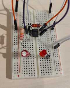
@mday I tried connecting the 555 like you described, but so far I am unable to get it to work. I have been playing around with it for a few days - the temperature dropped below 0 degrees Fahrenheit so indoor activities are prefered.
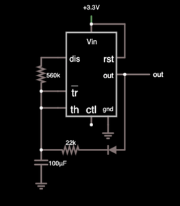
I really appreciate the diagram, but I suspect I might not have connected it correctly on my breadboard.
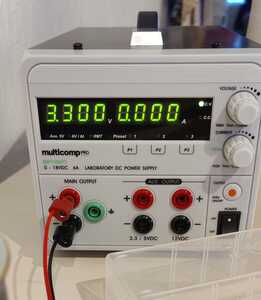
I am feeding it 3.3 volts, but I just cant get it to work.
Any ideas?
Kind regards, K
Hi @kabl, After reviewing your post, You might want to look at the NE555 data sheet, https://www.ti.com/lit/ds/symlink/ne555.pdf?ts=1671090405324&ref_url=https%253A%252F%252Fwww.ti.com%252Fproduct%252FNE555 , and you'll see that the minimum Vcc is 4.5 Volts.. so 3.3 volt supply won't work for you in this case. Abs Max rating is 18 volts, min: 4.5 volts, max current is 225 mA.. hope this helps you with your project.
regards,
LouisR
LouisR
@inst-tech ; I`ll try that after work today! Thank you 🙂
@kabl It sounds as if you missed this part of the YT video/blog
The 555 can operate with any voltage between 4.5 and 16 volts DC, and can sink or source up to 200mA. There are also low-power CMOS versions of the 555, such as the IN555, TS555, and LMC555.
First computer 1959. Retired from my own computer company 2004.
Hardware - Expert in 1401, and 360, fairly knowledge in PC plus numerous MPU's and MCU's
Major Languages - Machine language, 360 Macro Assembler, Intel Assembler, PL/I and PL1, Pascal, Basic, C plus numerous job control and scripting languages.
Sure you can learn to be a programmer, it will take the same amount of time for me to learn to be a Doctor.
@zander I kinda missed it, but I have picked up on it. Earlier in this thread ( https://forum.dronebotworkshop.com/postid/35697/) 3.3 volts was suggested. As I said in my original post, I have no education in this field and I might have read the schematics wrong, but I went with it. I will increase the voltage and try again after my shift has ended 🙂
No blue smoke yet, and I still have some spare parts, so I`ll keep going until it works like I want it to.
@kabl As a general rule, whenever working with a new chip, google 'datasheet 555' or whatever the chip name is, usually just the core number as the alpha portions are either mfg specific or a more specific chip. Here is what I found when I did that. See pic. Further reading shows it will operate under a wide voltage so further research may be needed. In this case since Bill (the man on screen in a Dronebot video) didn't say, it would be the default 5V. Have fun!
First computer 1959. Retired from my own computer company 2004.
Hardware - Expert in 1401, and 360, fairly knowledge in PC plus numerous MPU's and MCU's
Major Languages - Machine language, 360 Macro Assembler, Intel Assembler, PL/I and PL1, Pascal, Basic, C plus numerous job control and scripting languages.
Sure you can learn to be a programmer, it will take the same amount of time for me to learn to be a Doctor.
I got it working, finally 🙂 Thank you for all your help everyone, I`ve learned a lot.
Including that tantalum capacitors really do like correct polarity, apparently!
I wish you all a merry christmas, cheers.
Knut
I got it working, finally 🙂 Thank you for all your help everyone, I`ve learned a lot.
Including that tantalum capacitors really do like correct polarity, apparently!
I wish you all a merry christmas, cheers.
Knut
@kabl, Outstanding..you got it to work! Indeed, a Tantalum capacitor is an electrolytic type, and polarity sensitive. Also, there are voltage ratings on those types, so make sure you stay below those limits as they ban blow up sometimes with a bang!...lol
Be safe and have fun learning the all about electronics and programming mpu's
Merry Christmas to you as well.. And a happy new year!
Regards,
LouisR
LouisR
Hi, and a happy new year to you all.
After spending the holidays playing around with the 555 I have come across several schematics for the 555, with the PIN1 orientated upwards.
This might be a daft question, but why is the circuit presented like that, like in this diagram from an earlier reply in this thread? Why not have 4 pins on each side?
Kind regards, Knut


