@kabl I think all the mosfets I have used so far were 5V. I never did any 'math', just hooked them up and they worked. Here is a 'module' for 3.3V to 5V that has all the extra bits, this is my Canadian link so adjust as needed https://amz.run/6IRK
First computer 1959. Retired from my own computer company 2004.
Hardware - Expert in 1401, and 360, fairly knowledge in PC plus numerous MPU's and MCU's
Major Languages - Machine language, 360 Macro Assembler, Intel Assembler, PL/I and PL1, Pascal, Basic, C plus numerous job control and scripting languages.
Sure you can learn to be a programmer, it will take the same amount of time for me to learn to be a Doctor.
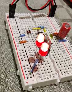
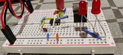
So I followed your tip on the mosfet, and I used a IRF520NPbF. To test it I used a 2.2k resistor from the OUT pin of the 555 and connected it to the GATE pin of the mosfet. To keep it as simple as possible I put two 5 volt LEDs in series and used the 9V battery I use to power the inverted timer circuit.
Success! Works like a charm, with correct timing.
The idea behind the use of a mosfet was to be able to control a circuit that needs higher current. So I brought out my power supply, connected it, 5V on a single LED, and I got this VERY strange behaviour. See the video, I apologize for the elevator music....
Seems like a Theremin-driven LED 😀
Any idea what is going on here? The timer circuit works fine when I reconnect the two LEDs and supply them from the 9V battery. The power supply is also working fine. I am a bit confused 😀 Any thoughts @dronebot-workshop / Bill?
Video of working setup, approx. 2 seconds light, approx. 38 seconds pause.
Hi @kabl,
i am not sure what you posted, but my PC is providing 20 seconds of elevator chimes and 40+ seconds of silence, but no video in either case.
-----
Moving back in time a little:
RE: Looking into that, it seems they have different forward diode voltage. As I understand it, this means how much the voltage will drop over the mosfet. This is a 3 volt logic, and looking at the TSM4NB60CI it has a forward diode voltage of 1.13 volts.
Your understanding of how MOSFETs work is confused with that of bipolar tranistors. When MOSFETs are used in a simple switch circuit like yours, they do not have a diode drop ... they behave like variable resistors.
The diode you see in the schematic symbol between the drain and source is reverse biased in 'normal' operation, so if we ignore the tiny leakage current (which can be as low as picoAmps for some devices), it has no effect on the circuit. The instances that diode comes into play is when then drain-source voltage becomes reversed (which can happen when switching inductive loads) or if the drain-source voltage exceeds the maximum rating (600V for the TSM device you mention). Assuming you wire the device up correctly, I don't think either of these cases apply.
The most important characteristics are Rds (on) and the gate (gate to source) voltage, Vgs, needed to achieve that Rds(on) value.
The data sheet at https://www.mouser.co.uk/datasheet/2/395/TSM4NB60_L1901-1918887.pdf shows:
Thus, the TSM4NB60CI is capable of switching up to 600V, but it needs 10V applied to the gate, with respect to source, to reduce its effective resistance from drain to source to around 2.5 Ohms.
In simple terms, this is a relatively high voltage switch, that needs a comparatively high voltage gate voltage to achieve that switching ... totally unsuitable for your needs.
The good news is that ther are more suitable devices, including MOSFETs that are often described as 'compatible with logic gate drive'. Note this is only a bit of advertising waffle ... the real information is in the data sheet numbers, but can be a useful indication to discover the data sheets worth looking at more closely.
I recommend you do some more searching for articles that describe how MOSFETs work, and our generous forum host, Bill @dronebot-workshop, 's excellent video would be a great start at https://forum.dronebotworkshop.com/2019/mosfets-and-transistors-with-arduino-2/
Best wishes, Dave
@davee Swift and precise as always, thank you for all the information. Bills excellent video has been seen a couple of times, prior to trying this.
The videos play nicely here, I am using Opera. To get below the 10MB limit they had to be recoded. However, I uploaded the videos, and the untouched video, to https://www.kabl.no/Video/
Kind regards, Knut
@kabl Looks like capacitive coupling to a floating INPUT.
First computer 1959. Retired from my own computer company 2004.
Hardware - Expert in 1401, and 360, fairly knowledge in PC plus numerous MPU's and MCU's
Major Languages - Machine language, 360 Macro Assembler, Intel Assembler, PL/I and PL1, Pascal, Basic, C plus numerous job control and scripting languages.
Sure you can learn to be a programmer, it will take the same amount of time for me to learn to be a Doctor.
Hi @Kabl,
Regarding the 4 videos, the first 2 have video, the second two starting VID only have sound ... as seen by both Firefox and Chrome, running on Windows 10.
Regarding the 'Theremin effect', which I can now see, I concur with Ron @zander, it looks like the gate to your MOSFET is floating ... gut feeling suggests the sensitivity is more than you would get with just the gate lead, so maybe the FET gate is connected at the FET end to breadboard conductor, and maybe even wire, but it is not connected at the driving end, so that you have several centimetres of conductor acting like a capacitor plate or aerial.
Best wishes,
Dave
The gate pin of the mosfet is connected to the out pin of the 555 using a 2.2kO resistor, as Bill showed in his video using the Arduino. The only long wires in my setup are the ones coming from the bench power supply.
What I find odd is that the mosfet behaves like I expected when the two leds are supplied by the 9 volt battery and the LEDs light up and turn off at the expected intervals. If the gate was floating, should it not behave in the same way if powered by a battery? If not, why?
The second difference is when powered by the battery, they have common ground. When powered by the power supply, it is a separate circuit.
The idea was to make a circuit like Bill did in the video about mosfet and the Arduino, and just substitute the Arduino with a 555 circuit. I made sure the voltage of the out pin on the 555 matched the voltage needed to trigger the gate (2-4 volts) of the mosfet but I am surely missing something here.
I`ll read up on the links, and try again 🙂 I am still waiting for the mosfet module to arrive, but I just wanted to try it out with the parts I had.
All the best,
Knut
Hi @kabl,
It is difficult to follow a circuit without a schematic, but I am suspicious about your 'second difference'. The two parts of the circuit should (generally, based I am trying to imagine your circuit) have their grounds linked at one point. If not, it could be the gate is effectively floating, with all the associated wire floating with it.
Best wishes, Dave
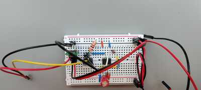
This setup works, the LEDs light up for 2 seconds, then idle for 38 seconds. 2 5 volt LEDs in series, fed 9 volts.
I will take similar pictures of the setup that does not work when I get back home after work. I only took video of the one that did not work, unfortunately. Thank you for taking your time helping me with this. I probably should not quit my day job just yet 🙂 On norwegian timezone, so the rest of the pics will be up in about 7 hours.
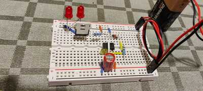
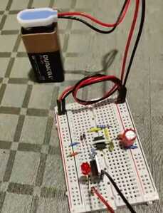
I have this screenshot from the video of the setup that does not work. The only difference is the ground to the third pin of the mosfet, and the positive to the LED is supplied thru an external powersupply. A little hard to discern from the screenshot, otherwise identical. Only one 5 volt LED, as the powersupply delivers 5 volts.
Hi @kabl,
Thanks for posting some more photos and well done for your progress so far.
It is rather tricky to work out your exact circuit from the photos, but I think my last comments are still appropriate. The negative connection from the battery and the negative rail from your power supply should be connected together at some point - if they are not, then the MOSFET gate is effectively floating, which would explain the "Theremin effect".
I recommend you draw out a schematic ... pencil and paper is fine ... to see what you have built. Post it on the forum if you have any questions or are still struggling to make it work - a photo is fine.
It is difficult to understand what is happening when you first start, but you will gradually begin to see patterns that make it easier.
Best wishes,
Dave
Hi all!
After a small break I had the time to sit down with this problem/challenge again. Some time away did the trick.
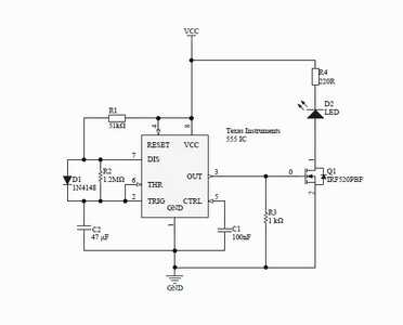
Fast recap; I had the 555 timer inverted, the timing right. Problem; make the output signal from the 555 control a MOSFET to be able to switch a device that requires a higher current.
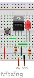
I took a look at this picture;
Courtesy of https://www.instructables.com/Transistor-Basics-MOSFETs/
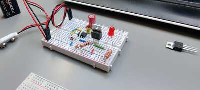
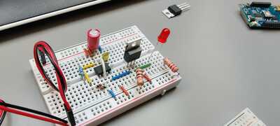
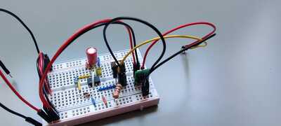
Using the previous breadboard I mounted a IRF520NPbF MOSFET, like in the following picture;
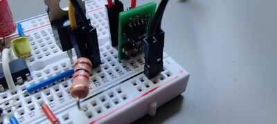
Added two photos, to make it easier to see all the connections.
This works, like a charm.
To add the secondary circuit, I added a 5V/1A switching regulator and made sure they had common ground. 9 volts in on the circuit feeds the 555 and the signal out on PIN3 (OUT) is approx. 3 volts, which triggers the MOSFET. The swiching regulator feeds 5 volts to the circuit I need to power, and the circuit draws about 500mA when active.
To be honest, I have no idea how to make a wiring diagram according to the standards, but I will try. I was able to make a PCB using Fritzing, and it works nicely.
I would like to thank each and every one of you for your help and contribution! Thank you so much 🙂
Now, next time I have some spare time on my hands I will make an effort to make a wiring diagram that makes sense.
Happy holidays to you all!
Hi @kabl,
Good to see you are making real progress.
As for circuit diagrams, my suggestion is is to start with 'old school' pencil and paper, to draw schematic diagrams, where you use symbols for components, rather than their physical appearance. There are loose conventions as to how they are best drawn, but don't worry about that to start with, just concentrate on ensuring they accurately show the connections.
Then gradually refine your skills, first by using applying simple conventions to make the diagrams easier to understand, then maybe look at using one of the CAD/CAE drawing programs. There are a number of free ones... some aim for simplicity, others for extended capabilities like simulation and/or PCB layout. Don't be afraid to use more than one ... once you have mastered one, the second one will have some new things to learn, but will also have a lot in common with the first!
The main thing is try to avoid having to learn too much at any one time ... figuring out which button to press next to use a CAD program, whilst also trying to work out what the drawing should look like is really hard. Even experienced CAD users often make rough sketches of bits of circuits on the back of an envelope, before entering them into the CAD system.
The Fritzing diagrams look nice, are clear, and are really helpful if when wiring a breadboard circuit, but (I think) actually make it quite difficult to interpret the circuit function. So whilst I completely understand why Bill and others use them to describe how to make something, I think it is also important to appreciate that schematic diagrams form the 'language' that helps to convey how a circuit works. Of course, if you want to publish a breadboard layout, the Fritzing drawing tool might be ideal, but regard it as one of your extensions beyond the first CAD/CAE tool.
-----
This suggested 'plan' is deliberately vague, and depending on your existing skills, time, priorities etc., could take you two months, or two years, or half a lifetime ... take it carefully and patiently, making sure you enjoy the ride!
Best wishes, Dave
@davee;
Thank you for all the tips. I will go about this the "old school" way.
I used Fritzing to draw lines on the PCB actually, I never built the breadboard model in the program. I have reasonably good abilities to think in 3D, so I made a PCB with lanes on both sides and connected all the lanes like I had on the breadboard. And it works.
Today I went out to buy some large sheets of paper, a nice pencil and printed out an overview with all the symbols for the different kinds of electronic components. We`ll see how much time I get to myself this weekend, perhaps I get around to it 🙂

