Hi all. I need some help designing a circuit. Let me give you some background. I want to use one of the piezo discs like you find in the LCD watches to make a buzzer - just like they do in watches. However, all my attempts to directly drive these discs, have resulted in a very quiet buzzer. I was wondering how the hell they did it back in the 1970s with a 1.5V battery? I was able to find this:
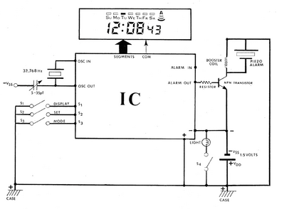
There is a section in here on the alarms! It shows the following circuit:
You can see the alarm circuit on the right. I guess you feed the PWM signal from the controller (I would be using an esp32) to the base of the NPN transistor. Then you have a resonator with the piezo and inductor in parallel. I was able to find a more detailed explanation here: https://www.ednasia.com/increase-piezoelectric-transducer-acoustic-output-with-a-simple-circuit/?rd=1
Note the author in the link above tries to pass this off as a "new" idea. Anyway, I started to read this and immediately had the following question:
The author states, "The electrical resonance frequency need not be the same as that of the acoustic resonance. In fact, if it is roughly 2× the acoustic resonance, the peak voltage across the transducer can be greatly increased.".
I think I can take that at face value even though he doesn't reference a source. So according to his example:
- Power supply = 5VDC
- L1 = 3.2mHy
- C(piezo) = 2nF
- Signal source frequency = PZ1, resonant frequency = 40KHz
- Signal source duty cycle is adjusted to eliminate a large current spike on turn-on
If I interpret this correctly, The mechanical (acoustic) resonance frequency is 40kHz so we would want to target an electrical resonance frequency of 80kHz. But if you do the math
so using his values of L=3.2mH and C=2nF
f=62850 Hz. - this isn't 80kHz.
But a few sentences down he says his oscilloscope shows, " * Violet = electrical resonance voltage across the transducer, 92Vppk. at 80KHz"
am I missing something?
fish
@fishbone I suspect the part labeled Piezo Alarm is a complete circuit not just a crystal.
First computer 1959. Retired from my own computer company 2004.
Hardware - Expert in 1401, and 360, fairly knowledge in PC plus numerous MPU's and MCU's
Major Languages - Machine language, 360 Macro Assembler, Intel Assembler, PL/I and PL1, Pascal, Basic, C plus numerous job control and scripting languages.
Sure you can learn to be a programmer, it will take the same amount of time for me to learn to be a Doctor.
@zander - that is quite possible. The diagram I show from the book above is really just to confirm the circuit from the link above is consistent with how they used to do it on the LCD watches. In the article from the link above, the author attempts to lay out some basic steps to design such a circuit. I want to try this but my math isn't working out. I want to make sure I am not overlooking something very basic.
-fish
@fishbone Ok, that's not something I have any experience with but others might.
First computer 1959. Retired from my own computer company 2004.
Hardware - Expert in 1401, and 360, fairly knowledge in PC plus numerous MPU's and MCU's
Major Languages - Machine language, 360 Macro Assembler, Intel Assembler, PL/I and PL1, Pascal, Basic, C plus numerous job control and scripting languages.
Sure you can learn to be a programmer, it will take the same amount of time for me to learn to be a Doctor.
@fishbone No, not always. Contrary to popular belief, I am human, I even admit my mistakes. LOL 😀
First computer 1959. Retired from my own computer company 2004.
Hardware - Expert in 1401, and 360, fairly knowledge in PC plus numerous MPU's and MCU's
Major Languages - Machine language, 360 Macro Assembler, Intel Assembler, PL/I and PL1, Pascal, Basic, C plus numerous job control and scripting languages.
Sure you can learn to be a programmer, it will take the same amount of time for me to learn to be a Doctor.
Hi @fishbone,
I have never played with these devices, but out of curiosity, I did a quick Google around. So just a few random notes from what I saw ... sorry it is not an answer, but I hoped something might trigger a thoght.
I tried the EDN ASIA reference, but there were no figures, excepting a generic circuit with no electronic resonant components. So I couldn't read the full story, an dit didn't help much.
-----------
As Ron @zander says, some devices are packaged with electronics, so it is only necessary to supply an appropriate dc voltage for the electronics, say 3-5V to enable it to be directly driven by an Arduino.
Others, are the 'raw' device. Typical drive voltages appeared to go up to about 200 V (peak), although lower voltages (say 20V) can be sufficient in appropriate circumstances. That voltage needs to oscillate at the frequency of sound to be emitted.
------------
The acoustic resonant frequency of the transducer appears to be a complicated quantity, not just a single fixed value. Sorry, I haven't followed it through properly, but I saw suggestions that it might be necessary to find it experimentally. Perhaps this has some connection with your observation of different frequencies when you try to calculate the electronic resonant frequency?
-------------
I suspect a significant part of maximising the acoustic output, especially when the power source is limited, is determined by the mechanical design surrounding the transducer.
The frequencies you mention are in the range 40 kHz to 80kHz, which are inaudible to humans .. These values suggest reference to an ultrasonic transducer .. not an alarm for a clock or watch, which presumably would need to be nearer 1kHz.
Best wishes, Dave
@fishbone One thing I notice is that your calculated value is 78.5625% of the 80kHz. If this part is a +-20% part as many are, then it is close enough.
I have ZERO familiarity as I never wore a watch until I got my first Apple watch a few years ago.
First computer 1959. Retired from my own computer company 2004.
Hardware - Expert in 1401, and 360, fairly knowledge in PC plus numerous MPU's and MCU's
Major Languages - Machine language, 360 Macro Assembler, Intel Assembler, PL/I and PL1, Pascal, Basic, C plus numerous job control and scripting languages.
Sure you can learn to be a programmer, it will take the same amount of time for me to learn to be a Doctor.


