I'm trying to figure out how to use a transistor to turn LEDs on and off from an Arduino. I realize that I could use a relay to do this but don't like the noise the relay makes and they are abrupt and you can't fade the on/off. I can also just drive the LEDs directly from the Arduino but at some point I might want to run things that take more current than the Arduino can supply. Plus I'd like to understand how transistors work.
My project is to make a Halloween decoration with red LED "Eyes" to hang in the shrubs outside my door that come on when a motion sensor is triggered. This year I did make a single set of eyes using a motion sensor to turn on the LEDs using a transistor and using a second transistor triggered by the same motion sensor to play a growl sound.
Next year, I'd like to have several sets of "Eyes" turn on and off at various rates when a motion sensor is triggered. I have a breadboard with a 5volt power supply. Positive is connected to the collector of the transistor (PNP BC558), the emitter is connected to a 47 Ohm resistor with feeds two red LEDs the are connected to the negative leg of the breadboard. I have a PWM pin (pin 7) of the Arduino connected to the base and I'm writing to that pin using analogwrite().
I'm trying to understand the strange behavior I see. When the value I write to the base is less than about 120 the LEDs blink on and off rapidly. Between about 120 and 180 the LEDs are off and over about 180 the LEDs are lit and seem to get brighter the higher the value goes.
I've tried various other transistors without much success. It seems like the NPN transistor I tried just dump the base voltage to the emitter and the LEDs would remain lit even if the collector was disconnected from power. I finally realized (I think anyway) the problem is two fold. First the pin is using PWM and at low values the PWM signal is turning the transistor on and off rapidly causing the LEDs to blink. I'm guessing that the middle range of values I've exceeded the base-emitter saturation limits and at higher values the voltage/current is leaking from the base to the emitter?
I'm thinking maybe using a resistor to limit the current to the base of the transistor and maybe a capacitor to smooth out the PWM signal?
I guess my main questions are: Can I use an Arduino to drive a transistor? If so, how? Are there output pins that are not PWM? Are resistors the way to limit voltage to the transistor base? The base-emitter saturation limit is about 700-788 mV depending on the current. How would I limit the current on the output pin of the Arduino.
Maybe I'm completely off base and the is a better way to do this?
Thanks
Peter
Perhaps you will find this video useful:
There is also an article that goes along with it. And yes, you do need a resistor on the base!
😎
Bill
"Never trust a computer you can’t throw out a window." — Steve Wozniak
@pajhum42 many pins can be made to be PWM or not via code, it's your choice. As they always tell me read the datasheets until you find a transistor that meets your requirements. They say there is a way to select on Mouser and DigiKey but I have troubles with them. Good luck.
First computer 1959. Retired from my own computer company 2004.
Hardware - Expert in 1401, and 360, fairly knowledge in PC plus numerous MPU's and MCU's
Major Languages - Machine language, 360 Macro Assembler, Intel Assembler, PL/I and PL1, Pascal, Basic, C plus numerous job control and scripting languages.
Sure you can learn to be a programmer, it will take the same amount of time for me to learn to be a Doctor.
@dronebot-workshop Yes, that video was very helpful. I've ordered some of the transistors and mosfets to try it out. thanks
@zander thanks, I've found some info on using resistors and capacitors to flatten out the pwm signal but not by using arduino code. I'll keep looking.
@pajhum42 Perhaps if you could explain more what it is you want the code to do to the PWM signal we may be able to help.
First computer 1959. Retired from my own computer company 2004.
Hardware - Expert in 1401, and 360, fairly knowledge in PC plus numerous MPU's and MCU's
Major Languages - Machine language, 360 Macro Assembler, Intel Assembler, PL/I and PL1, Pascal, Basic, C plus numerous job control and scripting languages.
Sure you can learn to be a programmer, it will take the same amount of time for me to learn to be a Doctor.
@pajhum42, HI...just following your post, and I found this link that I think should help you with both problems of how to use a transistor with an Arduino, and the code to use to control a PWM pin, or any pin for that matter..@dronebot-workshop Yes, that video was very helpful. I've ordered some of the transistors and mosfets to try it out. thanks
https://deepbluembedded.com/arduino-transistor-npn-pnp-switch-tutorial/
Let us know if you have any questions after you review the link I have included above..
regards,
LOuisR
LouisR
@zander What was puzzling my was the behavior of the LED. Using analogwrite to the output pin I expected the LED to gradually brighten as I increased the value written. What I observed was that for values below about 120 the LED would blink rapidly, for values between 120 and 190 the LED would be off and above 190 it would be lit and brighten as the value increased. What mistakenly expected was for the LED to brighten slowly over the full range of the of values written to the base. What I think is happening is that the PWM signal is alternating between 0 volts and 5 volts. I'm guessing now that what is happening is that the 5volt pulse is exceeding the base saturation value and causing the LED to be full on for brief periods. That doesn't really explain the other behavior but it is the best I can come up with for now. What I was wondering is it possible to turn the PWM signal to a pure analog maybe by using a resistor and capacitor . The comment by @zander made me do google search and I found an article that shows how to do that. I haven't had time to experiment with that yet. @dronebot-workshop also pointed me to a video that uses a different kind of transistor/MOSFET that looks promising.
@inst-tech Thank you, that looks interesting. It will take me a while to understand it and will probably have some questions. One thing I'm having trouble understanding is forward/reverse biasing. Another is the meaning of collector and emitter pins. I thought that source voltage went into the collector and came out of the emitter when the base received a signal. A lot of diagrams confuse me and seem to indicate the opposite, source voltage enters the emitter and exits the collector?
... source voltage enters the emitter and exits the collector?
First I would suggest you get to understand the basic concepts and their unit of measure.
The word "voltage" is a unit of measure electric pressure, like an inch or a centimeter is a unit of distance.
Also you might learn to use a multimeter to measure the volts, amps, ohms and so on in a physical circuit just as you might use a measuring tape to measure distance.
You might use a water analogy.
If you turn on a kitchen tap (faucet) and hold you finger over the outlet that is the PRESSURE (volts).
If you let the water run into a container and measure how much water runs into the container over a given amount of time that is CURRENT (amps).
If you turn the tap itself that will control the flow of water that is RESISTENCE (ohms).
A BJT is a current operated device. The amount of current between the collector and emitter terminals is controlled by the amount of current between the base and the emitter. A small base current controls a larger collector to emitter current thus you have amplification. This means a small voltage at the outlet pin of an Arduino can produce a small flow of electricity into the base terminal and that will control a larger electric flow through a load in the collector circuit like a motor.
A BJT device has diode characteristics. A diode can be thought of as a one way valve like the valve in a car tyre. You can get electricity to flow one way but not the other. If the there is no current between the diodes two terminals than it is said to be reverse biased otherwise it is forward biased.
A BJT acts like it has a diode between the collector to the base and between the base to the emitter. So if you want a current between the base and the emitter it must be forward biased.
@pajhum42 I suggest you first learn what PWM is, then using only that (no transistor) make that work. The example sketch in the IDE called Fade is a start. Also many of us here started with the Randomnerdtutorials and they have an example of fading a LED using PWM. See it at https://randomnerdtutorials.com/esp32-pwm-arduino-ide/
I have attached a bunch of pictures to get you in the ballpark.
AFTER this exercise is done, I suggest you take a basic course in electronics and then transistors before adding that to the working setup the nerds will teach you.
EDIT: Here is some more details on the ledc family of functions https://espressif-docs.readthedocs-hosted.com/projects/arduino-esp32/en/latest/api/ledc.html
NOTE: The above link and the RNT link is for ESP32, NOT Arduino UNO or NANO. For those and other boards you will need to find similar libraries.
EDIT2: If your interest is in the AVR (UNO , NANO etc) family, then check out the library AVR_PWM. See examples basic and Dynamic Duty Cycle.
NOW you can connect a transistor if you think it is needed.
First computer 1959. Retired from my own computer company 2004.
Hardware - Expert in 1401, and 360, fairly knowledge in PC plus numerous MPU's and MCU's
Major Languages - Machine language, 360 Macro Assembler, Intel Assembler, PL/I and PL1, Pascal, Basic, C plus numerous job control and scripting languages.
Sure you can learn to be a programmer, it will take the same amount of time for me to learn to be a Doctor.
@inst-tech Thank you, that looks interesting. It will take me a while to understand it and will probably have some questions. One thing I'm having trouble understanding is forward/reverse biasing. Another is the meaning of collector and emitter pins. I thought that source voltage went into the collector and came out of the emitter when the base received a signal. A lot of diagrams confuse me and seem to indicate the opposite, source voltage enters the emitter and exits the collector?
@pajhum42, Indeed..as a noobe, there is a lot to learn about basic electrical and electronics theory and application..don't get discouraged, it takes awhile for some of the concepts to really sink in.. First of all, you have to realize that solid state components, like transistors, are very complex and vary in how they work, and how to apply them in actual circuits. BJT ( bipolar-junction transistors) and Mosfet (Metal oxide Field effect transistors) operate totally different..BJT's are current driven, while Mosfets are voltage driven devices..If you are interested in learning electronics, then a lot of reading and studying will be required to understand the principles involved..Start with the basics, like Ohms law and basic DC circuit components of resistors, capacitors, inductor, batteries , etc, and then work your way up to how solid state components work. As a hobby, it's a lot of work, but very rewarding when you finely get a circuit design to work!...lol
I recommend that you start here:
as this is as basic as it gets.. and because its a video, you can review it as many times as you like.
It's well worth you investing your time into learning the basics first, as this will reduce your overall frustration with the problems of "why doesn't this work!" that you will surely encounter. Good luck, and be safe.. if you have more questions, just ask, and we'll try our best to help you.
Regards,
LouisR
LouisR
My feeling is we all have different learning styles. It helped me to have an intuitive or visual understanding of what was happening rather than just a bunch of formula to remember.
Using analogwrite to the output pin I expected the LED to gradually brighten as I increased the value written. What I think is happening is that the PWM signal is alternating between 0 volts and 5 volts.
That is correct. Calling it an analog write is misleading. When the frequency drops below a certain value you will start to see it turning on and off. However the advantage of using full valued pulses for a motor is you are applying the full force at any given time which equates to the torque (turning strength) of the motor so it will not stall at slower speeds.
The other concepts that I forgot to mention are the magnetic field and the electric field. They are associated with an inductor (coil of wire) and capacitor (two separated plates). Much of all this can be illustrated with simple circuits.
When I first played with a BJT component it took me a while to understand that the base current would try and maintain the collector current some multiple of the base current value. If you placed a resistor in the collector circuit the resistance between the collector and emitter would decrease to try and maintain that current value. Essentially you can use that to make a constant current source. An ideal battery provides a constant voltage source. Real batteries behave like a constant voltage source in series with an internal resistor. A battery that can deliver a high current has a low internal resistance. This is where electric POWER (measured in watts) comes into play. The higher the current the hotter the resistor (or battery) will become. Thus the need to have a wattage limit for any resistor.
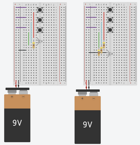
@michael-taggart I don't see any transistor. I see a battery, 3 push buttons, 1 resistor and an unknown device with 4 leads. Transistors have 3 leads.
First computer 1959. Retired from my own computer company 2004.
Hardware - Expert in 1401, and 360, fairly knowledge in PC plus numerous MPU's and MCU's
Major Languages - Machine language, 360 Macro Assembler, Intel Assembler, PL/I and PL1, Pascal, Basic, C plus numerous job control and scripting languages.
Sure you can learn to be a programmer, it will take the same amount of time for me to learn to be a Doctor.


