Hi @pajhum42,
Re: I'm assuming each led will get 1/2 of the current through the resistor.
If you are only making this one version of a circuit, and it is working with both LEDs at about the same brightness, then fine, but be aware you have been lucky.
LEDs of the same type have quite a wide 'tolerance' in their characteristics, depending on countless factors in the manufacturing process. In particular, the forward voltage drop can vary between samples.
If you have two which, by chance, are very similar, then they will probably 'play nicely' and take roughly equal shares. However, if they are not similar, then one will tend to take most of the power, potentially causing it to overheat and maybe fail prematurely, while leaving the other at reduced brightness.
For a 'reliable' circuit, it would be better to give each LED its own 'private' resistor, as this will enforce them to play nicely.
Good luck with deciphering my previous sermon. Obviously, if you get stuck, ask about it.
Best wishes, Dave
Hi Ron @zander and @pajhum42 ,
Re: Did you learn the difference and rationale for the Darlington transistor? Your circuit does NOT actually need a Darlington, just a basic BJT transistor like the BC548.
Perhaps the main lesson is that only a small (physical package as well as, current capacity and power dissipation) transistor was needed, because the load current was only 40 mA, not (say) 5 A.
It is also true that it didn't need to be a Darlington Pair, in that is easy to find a single transistor with current gain of around 100 minimum, so that 40 mA load could easily be controlled by 1 mA drive, an order of magnitude lower than the maximum limit that an Arduino or similar can typically provide. Had the load been (say) 5 A or more, the extra gain of the Darlington pair would become apparent.
Sometimes, low power Darlington Pairs (in small packages) are used to minimise the current drive requirement .. for example, as the input for a moisture indicator, where the base current would be current passing through the moisture.
In the 1960s, before a wide range of low cost MOSFETs were widely available, the Darlington pair circuit was often used, typically constructed from two bipolar junction transistors. In more recent times, MOSFETs have largely replaced this choice.
Best wishes, Dave
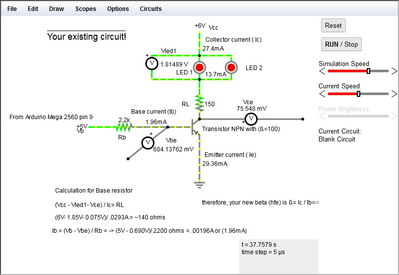
@pajhum42 , Looking at your circuit, and recalculating what you currently have, it appears that you are over driving the BC548 transistor, but it will give you about 29 mA ( .029A) of collector current, and a base drive of about 1.9mA ( .0019A)
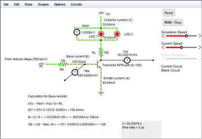
I've calculated what is required for the BC548 to get you to the 40mA you desire to drive each of the LEDs with 20mA each.
see the following simulation:
Ive assumed that the beta (hfe) is around 100, so that will give you ~ 400uA ( 0.0004A) of base current. I hope this will help you to understand how this is calculated.
Regards,
LouisR
LouisR
@inst-tech Louis what is the name of that tool?
First computer 1959. Retired from my own computer company 2004.
Hardware - Expert in 1401, and 360, fairly knowledge in PC plus numerous MPU's and MCU's
Major Languages - Machine language, 360 Macro Assembler, Intel Assembler, PL/I and PL1, Pascal, Basic, C plus numerous job control and scripting languages.
Sure you can learn to be a programmer, it will take the same amount of time for me to learn to be a Doctor.
@zander (Ron), I assume your asking about the software to do the simulations.. It's called Circuit Simulator Applet, https://www.falstad.com/circuit/@inst-tech Louis what is the name of that tool?
It's pretty handy for checking your calculations, seeing how the current flows, even wave form generation can be seen, so you can see Freq, voltage, current wave forms. It's pretty easy to use, but very generic as far as types of components are concerned..I mostly use it to illustrate basic principals as shown in my post.. but also to simulate circuit designs that I come up with before putting components on the breadboard to make sure I don't release the "magic smoke" .. 😆
Give it a try, it's a free on the web site.. easier to use than the more sophisticated simulators like TINA-Ti.
I also use TinkerCad, https://www.tinkercad.com/dashboard
as a tool to do Frizzling of circuits that print out and put into a binder along with spec sheets, and code.
Regards,
LouisR
LouisR


