@zander Sorry, I thought it said transistor, not resistor. Thank you for catching that!
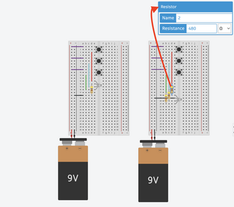
@michael-taggart They appear equivalent but the left solution uses fewer parts. HOWEVER, I think solution 2 on the right will allow multiple buttons to be pressed while the other solution may not, it depends on the R value and the RGB specs re current.
First computer 1959. Retired from my own computer company 2004.
Hardware - Expert in 1401, and 360, fairly knowledge in PC plus numerous MPU's and MCU's
Major Languages - Machine language, 360 Macro Assembler, Intel Assembler, PL/I and PL1, Pascal, Basic, C plus numerous job control and scripting languages.
This was created using the https://www.tinkercad.com/.
The light is a LED RGB. It doesn't give me the R value and RGB specs recurrent.
The R value is the same on the left as it is on the right for all of them. (Which is 480 oHm? Its just that one greek symbol.)
I assumed that it would be fine because there is no current until the button is pushed down (*The buttons are push buttons), but the other part of me was wondering if it was a problem to have the resistor after the RGB LED. I am assuming the flow on the left is safer because it goes through the resistor before going to the RGB LED, while the one on the right goes through the RGB LED first. But the OTHER part of me thought that the resistor is slowing down the current so it didn't matter at all.
@michael-taggart No, the concept is equivalent to plumbing. A restriction (resistor) anywhere in the circuit slows the flow of water in the entire circuit.
First computer 1959. Retired from my own computer company 2004.
Hardware - Expert in 1401, and 360, fairly knowledge in PC plus numerous MPU's and MCU's
Major Languages - Machine language, 360 Macro Assembler, Intel Assembler, PL/I and PL1, Pascal, Basic, C plus numerous job control and scripting languages.
Hi @michael-taggart,
As Ron (@zander) has pointed out, the single resistor circuit will probably behave in 'weird' ways if more than 1 switch is pressed at the same time, whilst the 3 resistor will allow 'coloured light mixing' by activating 2 or 3 LED elements at the same time. So for most purposes, I would suggest the 3 resistor solution would be more useful.
(By 'weird' ways, I haven't tested it, but I would guess that whilst the red button was pressed, only red would be seen, whilst pressing green and blue at the same time, might give an 'in between' colour. The exact operation would depend on the individual device, since it will be affected by the voltage drop of each element, and these have wide variations, according to the data sheet.)
You might like to look at Bill's (@dronebot-workshop) on RGB LEDs .. the first section of
https://dronebotworkshop.com/rgb-leds/
discusses these devices and shows how to use an Arduino instead of the mechanical switches.
You might even wish to show a progression, initially using mechanical switches, then with the Arduino. Note your the mechanical circuit is powering with 9V, whilst the Arduino output is 5V, so the series resistors are different values.
Good luck, Dave
It appears that your circuits, both of them are using an RGB Led, that is, an LED that incorporates 3 leds into one package...a red, Green, and Blue with a common cathode. and yes, The preferred way to connect the device is shown in ckt#2 with the common cathode to the negative post of the battery, and a resistor in each of the other three legs going to the switch and to positive battery..However, since LEDs ( Light Emitting Diodes) have a current limitation( about 30 mA for this particular one) the resistors have to be sized to limit the current to typically around 20 mA. In your schematic frizzling drawing, your showing a 9 volt battery to power this circuit, therefore the resistors need to be about 360 ohms to give you the 20 mA. This is because each leg of the diode is a separate LED and the forward voltage drop across that diode with be around 1.8 volts. So the formulae to calculate what size resistor is (Vcc-Vd)/Id= R where Vcc= battery or power supply voltage, Vd= forward voltage drop across the diode, Id= the current through the circuit, and R is the resistance required. So your power source is (9 Volts - 1.8 volts diode forward drop)/0.02A =360 ohms.
The .02A is 20 mA or 20/1000= amps. Hopefully this answers your question, but if you need more clarification, don't hesitate to ask...everyone starts outs this way as there is a lot to learn about the basics of electrical and electronic theory and application.
Regards,
LouisR.
i
LouisR
@zander what I'm trying to do is make a Halloween display with several pairs of red LEDs to place in the bushes outside my door for next years trick-or-treaters. I plan to use an Arduino to make the eyes come on at different times and lengths of them. I'll use a PIR to trigger the sequence if eyes turning on and off. I've made this work with a single pair of LEDs using the PWM pins but I'm planning on using more LEDs than the Arduino can drive by itself. I want to use the transistors to use a second power source to power the LEDs. I've done this using relays but relays have an audible click when triggered there is no slow on/off with a relay. @dronebot-workshop listed a video showing how to use BJT and MOSFETs that I'll try.
@inst-tech thank you, that looks useful. I'll take some time to study it.
@robotbuilder I get that I should have said current instead of voltage. I've been reading about transistors and watching youtube videos. I think I'm gaining some understanding. Maybe you could confirm that I've gotten it right.
For an NPN transistor, current enters the base and flows out the emitter. The load is between the positive side of the power source and current flows through the load into the collector of the transistor when current is applied to the base. The emitter is connected to ground. I'm guessing that the reason the load is before the transistor is we don't want any interaction between the base current and the load.
For PNP transistors the positive is connected to the emitter and current flows out the base when the base voltage(?) is lower than the emitter voltage. When the base and emitter have the same voltage, no current flows and the transistor is off. Dropping the voltage on the base allows current to flow from the emitter to the base and the transistor turns on. The load is after the NPN transistor for the same reason it is before the PNP transistor.
One thing I haven't figured out yet is why the pin that current flows into is called the emitter of a NPN transistor. On a PNP transistor the names collector and emitter make sense to me but on a NPN transistor they seem backwards.
This might be useful reading.
https://www.douglaskrantz.com/ElecElectricalFlow.html
Now think of a transistor as having two diodes connected internally as shown here,
https://learn.sparkfun.com/tutorials/transistors/symbols-pins-and-construction
You can use that fact to identify a transistor as being NPN or PNP using a multimeter.
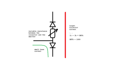
Think of there being a variable resistor between the collector and emitter.
This is automatically adjusted to try and keep the collector current at some value determined by the base current.
The collector_current = base_current * BETA where BETA is greater than one (maybe 1000) and thus you have amplification.
A small current controlling a larger current by adjusting the resistance between the collector and emitter.
By the way the transistor is not turned ON/OFF by the base current being present or not. It is turned ON when the resistance between the collector and emitter is close to zero and turned OFF when the resistance between the collector and emitter is very high.
Confused 🙂
To enlarge an image, right click image and choose Open link in new window
@robotbuilder I was going to ask some questions re the diagram, like how does current flow in both directions, and how does one current flow counter to my age groups positive to negative, BUT don't answer; I subscribed and got the entire sparkfun document on how transistors work so will use their explanation for my understanding.
Is the idea of a resistor in the middle just a conceptual thing, or is there some magic that allows the transistor to act as a variable resistor? This is the first I have heard of such a thing, and frankly, it is quite disturbing as it appears to be some magic instead of science.
First computer 1959. Retired from my own computer company 2004.
Hardware - Expert in 1401, and 360, fairly knowledge in PC plus numerous MPU's and MCU's
Major Languages - Machine language, 360 Macro Assembler, Intel Assembler, PL/I and PL1, Pascal, Basic, C plus numerous job control and scripting languages.
@robotbuilder Thanks again, I found a lot of useful documentation on the Learn Sparkfun site. In fact I will direct newbies here on the forum to the https://www.sparkfun.com/engineering_essentials in the future.
First computer 1959. Retired from my own computer company 2004.
Hardware - Expert in 1401, and 360, fairly knowledge in PC plus numerous MPU's and MCU's
Major Languages - Machine language, 360 Macro Assembler, Intel Assembler, PL/I and PL1, Pascal, Basic, C plus numerous job control and scripting languages.
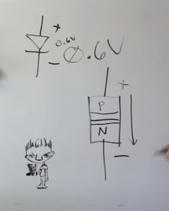
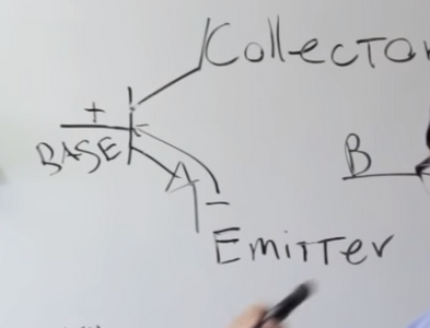
@robotbuilder I followed your link and followed it further to the Sparkfun video about how transistors work. He explained diodes first since a transistor can be though of as two back to back diodes. So far no problem, but when he showed the current flow for the transistor even my faulty memory saw a lie. The diode passes current normally from P layer to N layer (see pic from vid) but when he explained the NPN transistor he said the current across the diode was N to P. BOTH CAN'T BE TRUE!!! What gives?????
If someone better explains how a transistor works or can show me why the presenter is not lying, I would be very grateful.
I am tagging in @davee Dave as he may have a canned sermon that will answer my mystery.
First computer 1959. Retired from my own computer company 2004.
Hardware - Expert in 1401, and 360, fairly knowledge in PC plus numerous MPU's and MCU's
Major Languages - Machine language, 360 Macro Assembler, Intel Assembler, PL/I and PL1, Pascal, Basic, C plus numerous job control and scripting languages.


