I purchased these from Amazon a month ago and have been unable to get them to work. This version only the RxTx pins on the Arduino. I still unclear whether you need to use AT commands to set them up or a Lora library. There seem to be numerous versions on youtube. I can’t wait to take advantage of their long range capabilities. Help plz.
Hi @gtmize,
Sorry, I haven't any experience of these modules, so just a few preliminary comments.
- From the limited data on the web, the REYAX RYLR896 on Amazon is a 3.3V only module. Connecting directly to 5V Arduino like Nano or UNO, may well damage it.
- Make sure the GND (maybe labelled 0V, etc ) of the Lora module connects to the GND of Arduino
- Make sure Lora module has an adequate power source ... taking 3.3V from an Arduino or ESP to drive a transmitter is pushing your luck, though it sometimes works, in general, don't bother trying!. (Depends on factors, like transmitter power, which I haven't looked into for this preliminary reply.)
- There are obviously libraries (though I have no experience of them). But 'AT' codes date back to modem times of a few decades ago, and were designed to be semi-human understandable. Hence, I would expect to be able to set up a very minimal terminal style conversation, in which you send an AT command and get a response back ... looking at the Command guide, sending just AT should provoke a +OK reply, showing that you are in communication with the Lora module.
- Command guide at https://reyax.com/upload/products_download/download_file/LoRa-AT-Command-RYLR40x_RYLR89x_EN-8.pdf
As I say, I haven't got such a module, and I have only spent 5 minutes looking at the web, so the above is based on what I saw and fading memories of using modems three or mores decades ago, so just treat as guides to consider, not proven facts.
I presume you have seen Bill (@dronebot-workshop)'s video + blog on Lora, but remember he chose the Adafruit module, which comes with 3.3V-5V logic interface and power regulator on board, unlike the REYAX one.
Best wishes, and good luck, Dave
Yes, have powered it with 3.3v, watched Bill's Vid ( different pinout ) , and many other UTube vids, and reviewed the AT commands. But thanks for your thoughts. Gary
Hi Gary @gtmize,
Sorry, I can only offer hints. I assume you are using 3.3V microcontroller, like an ESP32, Pico or one of the newer Arduinos?
If you have an oscilloscope, then I would also suggest you look at the UART Tx and Rx signals, but of course, 'scopes are moderately expensive, so I realise that is easier to suggest than actually do.
Whilst I haven't actually done it, I would have expected it to be possible to get the module to respond to the simple modem AT commands, with OK, etc., provided it is correctly connected and functional ... I recall doing that with modems some decades ago, including debugging when there was a problem, like a faulty or wrong connection!
Getting two modems (or Lora modules) to talk together can be a bit more fraught, as there are now twice as many connections. etc. that all need to work properly at the same time. So get each end to talk back first.
You might consider exactly following Bill (@dronebot-workshop)'s set up ... it is clear from his videos & blogs, that unlike some YouTube presenters, he very carefully prepares the material, to make sure it will work ... and sometimes that involves trying and discarding other stuff, that is more troublesome. So whilst neither Bill nor I give any guarantees, I think your chance of success would be much higher. Unfortunately, that does mean buying at least one more module.
I wish you luck, with whatever you decide. Best wishes, Dave
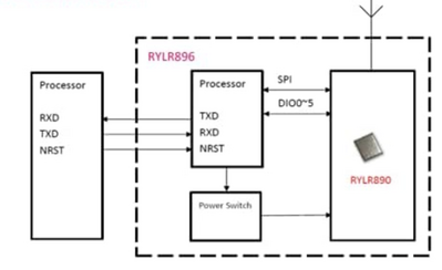
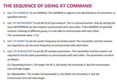
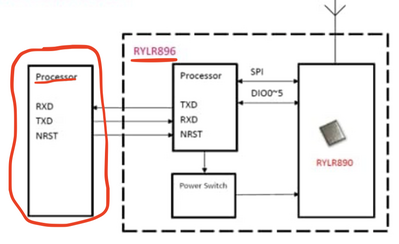
@gtmize FYI @davee The wiring directions are pic 1, the AT commands are pic 2. As far as code, I think you just want to read AT commands from Serial (in) and write them to Serial (out). If not clear, look at the following link under Serial USB Examples. See sample code at end.
int incomingByte = 0; // for incoming serial data

void setup() {
  Serial.begin(9600); //initialize serial communication at a 9600 baud rate
}

void loop() {
  // send data only when you receive data:
  if (Serial.available() > 0) {
    // read the incoming byte:
    incomingByte = Serial.read();

    // say what you got:
    Serial.print("I received: ");
    Serial.println(incomingByte, DEC);
  }
}
First computer 1959. Retired from my own computer company 2004.
Hardware - Expert in 1401, and 360, fairly knowledge in PC plus numerous MPU's and MCU's
Major Languages - Machine language, 360 Macro Assembler, Intel Assembler, PL/I and PL1, Pascal, Basic, C plus numerous job control and scripting languages.
My personal scorecard is now 1 PC hardware fix (circa 1982), 1 open source fix (at age 82), and 2 zero day bugs in a major OS.
Ron: Sorry, it's too late for my grey cell tonight, so this might be rubbish, but isn't your script talking to the Arduino processor, not the Lora modem, which is a second level away. ie you have to make the Arduino act as a message relay?
I think it should be possible to use one of the FTDI or similar USB to UART boards to connect to the Lora board, and then use a terminal program running on the PC in the way your script is hinting at, but with no hardware to try it out, manually typing AT commmands, but this is only a stepping stone, albeit a useful one.
But since I don't know if the software packages are configurable to this Lora module, so I haven't recommended it to someone unfamiliar with modems, etc.
Gary:
Sorry, it's stupidly late in the day for me, and I haven't looked at the software, but I assume the pin settings you mention refer to the another board ... maybe the Adafruit board that Bill used? It might be possible to use that software with your board, I don't know, but it is usually hard to jump from one hardware design to another, without analysing both board circuits, and then similarly going through the software, making changes or configuring, etc.. Obviously it probably can be done, but I would never recommend it, unless you are familiar with the products, as the learning curve can be steep. My recommendation is to start with something that is more likely to work. I haven't personally followed Bill on this project, but I trust he will have chosen a combination of hardware and software that is extremely likely to work, but only if you follow it to the letter. Sorry, if this means buying a new module, but I think you are more likely to succeed.
Best wishes, Dave
@gtmize FYI @davee Your board is entirely different from Bill's board. Did you read my previous post? If you did, then I am very concerned for you. Here is the post from me earlier https://forum.dronebotworkshop.com/arduino/rylr896-lora-module-setup/#post-47606
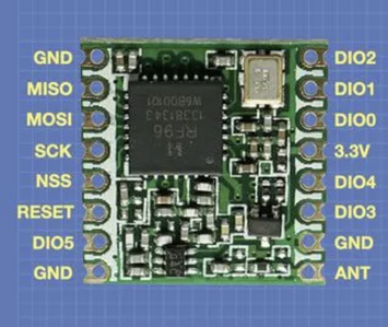
Here is a picture of one of the LORA boards Bill used. Notice a difference? It has 16 pins, yours has 6 at most.
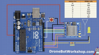
The next pic is of Bill's UNO connected to a LORA board. Counting tyhe power and antenna there are 10 connections. Your board has a max of 6. Bills sketch is using SPI I think, yours can only work with Serial UART.
Inside your module, is a LORA board and some sort of microprocessor. Your boards interface is Serial, the embedded processor then converts that to SPI to talk to the LORA.
Your board can work, but I can't tell if you canj manipulate the LORA control registers to get the maximum range and performance.
First computer 1959. Retired from my own computer company 2004.
Hardware - Expert in 1401, and 360, fairly knowledge in PC plus numerous MPU's and MCU's
Major Languages - Machine language, 360 Macro Assembler, Intel Assembler, PL/I and PL1, Pascal, Basic, C plus numerous job control and scripting languages.
My personal scorecard is now 1 PC hardware fix (circa 1982), 1 open source fix (at age 82), and 2 zero day bugs in a major OS.
@davee His board does NOT expose any LORA pins.
You could do as you say to accomplish what I posted earlier, I went that way as I thought it was more noob friendly.
In any case, his board is NOT a LORA board, it has a LORA board on it, but none of the LORA pins are exposed. See my prev answer that I FYI'd you on.
First computer 1959. Retired from my own computer company 2004.
Hardware - Expert in 1401, and 360, fairly knowledge in PC plus numerous MPU's and MCU's
Major Languages - Machine language, 360 Macro Assembler, Intel Assembler, PL/I and PL1, Pascal, Basic, C plus numerous job control and scripting languages.
My personal scorecard is now 1 PC hardware fix (circa 1982), 1 open source fix (at age 82), and 2 zero day bugs in a major OS.
Hi Ron @zander,
I did see the diagrams you posted ... in fact I had previously seen the same ones on Amazon and my replies were partly based on it.
I agree, there appears to be a 'general purpose' processor of some sorts on the board, acting as an interface to the Lora module... I don't think that stops it being a 'Lora board', as I presume Lora essentially refers to the RF transmissions and receptions side, not the user facing interface. (i.e. I am not aware of any part of the Lora interface says that the connections must be UART or SPI or xxx, on the user side, although there maybe recommendations or de facto norms, to that effect to assist mix and match designs.)
But because the 'general purpose' processor can completely change the user facing side interface, I have twice recommended following Bill's video+blog to the letter, and abandoning this board, not because it is impossible to use, but because it may require a completely different approach, with as yet-to-be identified or yet-to-be written software, making it too difficult to be supported on this forum by volunteers like me, who have neither the board, nor the interest for such ventures.
Bill takes a lot of trouble to select hardware that 'plays nicely' ... of course, alternative hardware may also work, but those who choose an alternate must also be in a position to debug it, when things get sticky, which often means lots of experience and be in a position to apply 'scopes and the like.
----------
I don't want to spend a lot of time looking at the details of this board, but at first glance, it looks like the interface is 'reminiscent' of the Hayes modem interface, although how closely it follows the commands I don't know. I would imagine it can perform Lora compatible transactions, but that does not mean it is (or isn't) compatible with any of the libraries available for Arduino systems, as one or more may have designed for it. I just feel it is beyond our reasonable scope to track them down, etc.
---------
And sorry, but with due respect, I still think your sketch is flawed, albeit I may not have clearly explained why.
Arduino-style boards default "Serial.xxx" communications go via the USB port, to the host PC. Hence, Serial.println("Hello"); will be visible on the Arduino IDE monitor window. and also, your sketch will attempt to read a byte from the PC's keyboard buffer, not the Lora board.
For processors with more than one UART, then the additional UARTs can be accessed by "Serialx.abcd" commands, where x is an integer like 1,2 or 3, depending upon how many UART ports are available on that processor/board, (and abcd is a method of Serialx, like read or print).
In summary, to give a meaningful sketch, this requires knowledge of the Arduino-stye board chosen, its precise connections to the Lora board, Baud rate setting, and so on.
-------
Best wishes, Dave
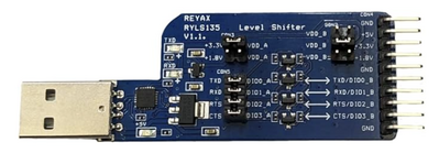
@davee FYI @gtmize I think we are mostly in agreement, but I didn't give as deep and thorough an answer. I did forget to mention that between the board and the PC a special adapter is needed as stated on the Amazon page.
HOWEVER, although this would work, it is overkill as that adaptor board can be directly connected to the PC (although their diagram does show an arduino in between). Then just like in the old days simply doing (from an old memory) echo (serial) AT will work. Sorry I forget what the PC (serial) is.
BOTTOM LINE get a LORA board. Either a raw board such as the raw board HERE the Adafruit version HERE or these Heltec ready to go (I have these as well) HERE
Since the OP appears to be interested in long range operation, there are a some settings that have to be made and I don;t know how that can be done with AT commands. I have attached a pic of most not all the setup that has to be done.
First computer 1959. Retired from my own computer company 2004.
Hardware - Expert in 1401, and 360, fairly knowledge in PC plus numerous MPU's and MCU's
Major Languages - Machine language, 360 Macro Assembler, Intel Assembler, PL/I and PL1, Pascal, Basic, C plus numerous job control and scripting languages.
My personal scorecard is now 1 PC hardware fix (circa 1982), 1 open source fix (at age 82), and 2 zero day bugs in a major OS.
I guess I've been mislead by reviews posted on Amazon for RYLR896, and Youtube videos indicating success is using the RYLR896 Lora board and only RxTx pins. I'll buy ones with the Lara pins exposed as you and Dave suggested.
Thanks for your help.
Gary Mize
Hi Ron @zander & Gary @gtmize,
The AT command set document is at
LoRa AT Command RYLR40x_RYLR89x_EN.pdf (reyax.com)
I'll leave deciding whether it is sufficient to others, although I did notice some of the same parameters being mentioned.
--------
Experimenting etc. is always a challenge ... and starting in a new area, often means climbing a high wall, with lots of 'small' things to spot or overcome, which initially seem far from small. As you get more experience, you find ways to overcome these challenges, and it becomes easier, but then you start something new, and find you are bottom of another wall, albeit you may be able to transfer a few tricks from the old wall to the new wall, so your progress is a bit quicker.
Personally, if I can get access into a new area, with some help from a trustworthy source, I think it can save a lot of time and effort getting those initial footholds. Hence, my suggestion to start with Bill's material and follow it to the letter. Once you get some experience, by all means get a bit more adventurous, but try to do it in a progressive way, without unnecessarily making big leaps into the unknown. When someone shows something on YouTube or in a review, it might be fake or inaccurate, or it might be accurate, but set up by someone with a lot of background knowledge and experience, who 'forgets' to point out all the pitfalls, tricks, etc. These situations can be very frustrating!
Best wishes and good luck, Dave
@davee @gtmize WOW, I did not see that document, where was it mentioned?
DUH, Now I think I get it, that processor on the reyax board is an enhanced HAYES AT command decoder with the extensions needed to drive a LORA chip. That's ok as long as ALL the LORA facilities are exposed.
The reason I used an arduino between the pc and reyax board was because of what I saw in the attached pic. NOW I can see that 'processor' could mean PC especially with the following (2nd pic) between the PC and the reyax board.
Personally I would rather work directly with the LORA board but maybe I am missing something re using the old Hayes AT commands.
First computer 1959. Retired from my own computer company 2004.
Hardware - Expert in 1401, and 360, fairly knowledge in PC plus numerous MPU's and MCU's
Major Languages - Machine language, 360 Macro Assembler, Intel Assembler, PL/I and PL1, Pascal, Basic, C plus numerous job control and scripting languages.
My personal scorecard is now 1 PC hardware fix (circa 1982), 1 open source fix (at age 82), and 2 zero day bugs in a major OS.
@gtmize Gary, here are the parts I ordered to experiment with LORA. They are a bare LORA board, a PTSolns prototyping kit (you will see why it is needed if you look at the bare board closely (2mm vs 2.54mm)) and a pair of Heltec LORA radios kit. There are even newer versions of the Heltec gear, you may want to look at their website. I have the board manager for them if you need it.
Bare board at LINK prototype kit at LINK and Heltec kit at LINK but also check heltec.org for the latest.
NOTE: My stuff is from amazon.ca. If a different country, change the .ca to whatever. ALSO understand and deal with the frequency allowed in your country.
Good luck, I am still about 20 ft short of where I want to get to but some new antennas should solve that.
First computer 1959. Retired from my own computer company 2004.
Hardware - Expert in 1401, and 360, fairly knowledge in PC plus numerous MPU's and MCU's
Major Languages - Machine language, 360 Macro Assembler, Intel Assembler, PL/I and PL1, Pascal, Basic, C plus numerous job control and scripting languages.
My personal scorecard is now 1 PC hardware fix (circa 1982), 1 open source fix (at age 82), and 2 zero day bugs in a major OS.

