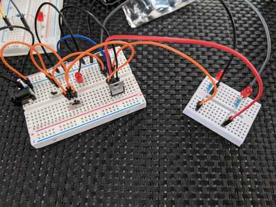
I wanted to make a very simple linear voltage regulator, which can be switched between 3.3V and 5V output. I'm only connecting each output to an LED+resistor for visual confirmation. Also, if I do anything stupid, I'm only destroying those components! There are no capacitors to smooth the output and there's no diode for reverse protection; my brain is still getting used to visualising and building simple circuits so this is enough wires for me at the moment. Anyway, here's the beast in all its glory!
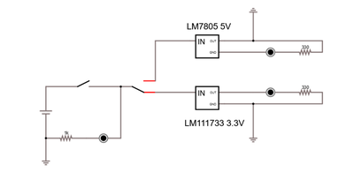
I quickly knocked this up in circuitjs, as I'm not yet familiar with LTSpice or EasyEDA. They all share a common ground. I think this is what I have; my house didn't burn down and it appears to work! Bonus!
If I revisit it, I will do some more reading on adding capacitors and a diode, but that's for another day.
Should the GND output of the LM7805 be connected to the ground?
Should the 5v and the 3.3v have different resistor values for their LED?
https://www.hobby-hour.com/electronics/ledcalc.php
I believe it should go to ground. I can't remember exactly what resistor values I used; the ones in the schematic may not be correct. I picked arbitrary values as I was in a rush. 🙂
This is the module I use on my breadboard which is sort of what you are doing.
This also gives the circuit diagram.
https://www.pcboard.ca/breadboard-power-supply-with-3-3v-and-5v-outputs.html
Thanks! Yes, I guess mine is the simplest variant of this. I also have one of those breadboard power supplies, but I don't use it.
Should the GND output of the LM7805 be connected to the ground?
Should the 5v and the 3.3v have different resistor values for their LED?
https://www.hobby-hour.com/electronics/ledcalc.php
I may have used a 1k resistor for the power supply LED (I should have labelled my components in the schematic, note for next time). I think I used 220 or 330 for the 3.3V and 5V LEDs, which is overkill according to that website. I only have minimal selection of resistors and these are definitely values I have.
I'm using a breadboard to build this up. What's the next stage after a breadboard, if I want to try to make something a little more permanent? Perf boards - https://bc-robotics.com/product-category/prototyping/perfboards/?
I built something similar with one regulator.
I put a resistor in series with the ground lead of the regulator.
When the resistor is bypassed by a relay it regulates to its normal voltage.
When the resistor is not bypassed it is in series with the ground sense of the regulator and this raises the regulated voltage.
But having two regulators would be a more rock-solid design.
Thanks dw.
I watched a video last night which compared the LM7805 to a buck converter. With an input voltage of 12V and a load of around 400mA, the LM7805 was constantly shutting down after about 150 minutes due to heat, while the buck converter was fairly cool in comparison.


