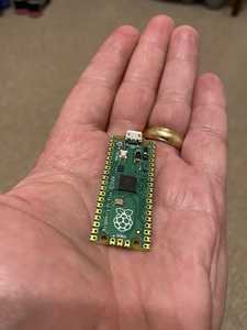
@whitneydesignlabs, you so right about how surprisingly small it is. Very flexible form-factor as well, with the multiple connection options for the pins on around the perimeter. You can surface mount the thing on another circuit board very easily without adding any height. The thinness is striking. The micro-usb and bootsel button are the only thing making this little board 3D, practically. I've included a pic of the pico in my hand so you can get a sense for the scale.
Does the Pico run an RTOS of some kind? I may have missed it in all the material, but it doesn't seem to be mentioned.
The micro-usb and bootsel button are the only thing making this little board 3D, practically.
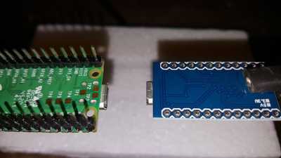
The other thing I noticed, and I think I am correct, is the USB connector appears to have metal tabs soldered through the board, increasing durability. I have not wrenched on it to find out, however... 🙂 One complaint I read about Arduino Pro Micros is that the USB connector is fragile, and has given people fits trying to re-solder it back on after accidentally ripping it off the PCB. On the left is the Pico, on the right is Pro Micro.
Scott
Imagine by thought, create, don't wait, Scott.
Does the Pico run an RTOS of some kind? I may have missed it in all the material, but it doesn't seem to be mentioned.
I had to google up the acronym RTOS to learn what it was. My results seem to indicate the answer to your question is, yes. It seems pretty new, and scantily documented at the moment.
Github, Raspberry Pi Pico & FreeRTOS
Scott
Imagine by thought, create, don't wait, Scott.
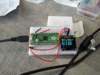
I can state unequivocally that the Pico can take a licking and keep on ticking. I was so excited to get mine that I made the classic noob mistake of soldering on the header pins out of alignment making it useless to use on a breadboard. So I had to de-solder all 40 pins, clean up the connections and re-solder new headers. After all that mess, the Pico still works perfectly. Thanks to Paul at learn electronics YouTube for the push in trying out the SSD1306 OLED. I had a color OLED, but it works the same as discussed in the video.
Cheers!
--->Sean
(◕(' 人 ') ◕)
I wish someone would bring out a version with pins soldered on - I don't have a soldering iron. 😐
I wish someone would bring out a version with pins soldered on - I don't have a soldering iron. 😐
Brand new from Pimoroni.
Cheers!
--->Sean
(◕(' 人 ') ◕)
I wish someone would bring out a version with pins soldered on - I don't have a soldering iron. 😐
I found that when I started getting back into MCUs I needed some tools and a soldering iron was key found a good one on Amazon for <$11.
If your code won't compile, have another glass of bourbon. Eventual the problem will be solved.
I picked up a pair of Picos on Saturday. Impressive little MCUs! I like the way you can re-assign the GPIO pins to perform different functions, eg PWM, I2C, SPI, SIO, UART, PIO. So far I’ve used PWM to control the brightness of a couple of LEDs on a single slice. I’m going to attempt to port some robotics sketches that I’ve written. So I need DC motor control, LED control, analog sensors, piezo buzzer, IR emitter/receiver pairs.
I was wondering if anyone has tried to max out the use of PWM slices in a single app? With 8 slices I was thinking of trying: 1 slice for LEDs running at 1kHz, 1 slice for a dual DC motor controller running at 20kHz, 1 slice for a piezo buzzer running at 1kHz, and 2 slices for IR emitters running at 38kHz. Is this even possible without Bourbon?
Tom
To err is human.
To really foul up, use a computer.
@thrandell I have no experience with any of that, but IIRC re-assignable pins are also common to the arduino family so maybe also research there for similar issues and motivation. I haven't even unpacked some of my Picos yet, todo list too long!!!
First computer 1959. Retired from my own computer company 2004.
Hardware - Expert in 1401, and 360, fairly knowledge in PC plus numerous MPU's and MCU's
Major Languages - Machine language, 360 Macro Assembler, Intel Assembler, PL/I and PL1, Pascal, Basic, C plus numerous job control and scripting languages.
Sure you can learn to be a programmer, it will take the same amount of time for me to learn to be a Doctor.


