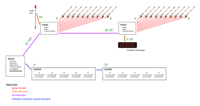
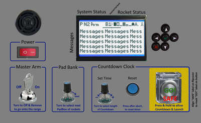
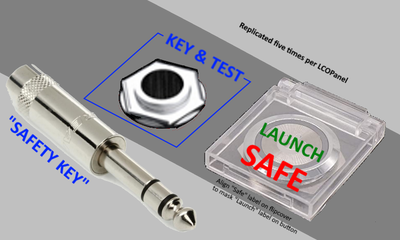
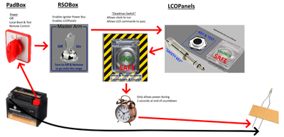
At the risk of embarrassing myself... Here is the current plan for a 20+ model rocket launch control system that I am building for the Cub Scouts.
Robert from Charlotte, NC, USA here. I have been the Rocketry Station Lead at Webelos Adventure Camp for five years. Yes, you read that correctly, putting black powder in the hands of fourth and fifth graders...
To celebrate, I'm upping the ante: building a custom launch control system.
You see we normally have ten Scouts/LCOs "drag race" their rockets at a time. But that then leaves us struggling to push through enough load/fly/recover cycles to get everyone through in time to get to their next station of learning & fun. We'll have 20-40 Scouts learn about engineering, rocketry, & safety; and build kits to fly _twice_ every hour. We fly once, talk to them about timing, winds, other factors beyond control that left us scattered about the rocket range....then how to adjust for those factors, and fly again to see the results.
But it takes so long to do at just ten at a time. So let's do twenty, thirty--or more! But as a seasoned RSO, there is _no_way_ that I am handing out twenty plus individual launch controllers & "keys" to fidgety fourth graders! So to compensate, let's build a unified launch control system--something with multiple layers of systemic safety controls! Each PadBox has a power disconnect. The RSOBox has a removable "Master Arm" key and a "dead man" countdown switch. And the individual Scouts/LCOs have to insert a "key," flip open a cover, and hold their launch buttons. Only with launch power, RSO, LCOs, -AND- Countdown terminal window (two seconds at end) in agreement can anyone actually send current to an igniter!!!
By making it modular, we can make it easier to store and to drag out to the field. We can also make it easier to swap out components, if some channel fails. We can scale down to lend out minimal parts to small launch events. We can scale up/out by building more PadBoxes & LaunchPanels to have tens, hundreds, even the _entire_camp_ launch at once!
How does this look? I'm finally learning enough KiCAD not to totally embarrass myself with the electrical schematics... Also getting it down to a set of smaller Arduinos! But boy do I need to work on the electrical calculations. (Forgotten so much in the 30 years since I was a Red Cross volunteer first learning electronics!)
All suggestions are welcomed! Thanks in advance.
I do find it an odd choice to use I2C through an RJ45. The range is limited and susceptible to interference. I would have expected RS485 for all of it. You could also look into using an addressed protocol like DMX512. It can be sent over cat 5. That is mostly what we use for pyro controllers in entertainment pyro. There are some exceptions though. You might also consider this for your cable run out to the other boxes. I would also be worried about plugging in the wrong connector to the wrong place. I thought I saw 24V on one. I have heard of using Cat6 for 48v but for very low current, so I could only assume that you would be ok but that wouldn't be my choice.
What is the purpose of the ring connection on the 1/4" TRS phone plugs? It says fault but doesn't go anywhere but you will get a fault detected when plugging and unplugging. Also, I know from years of experience that they are the worse connection and should have been retired long ago. They don't' always connect and worn out/dirty very fast. Using these outdoors may be a pain. If you mount them on the side of something and not on top it will be a bit better but expect problems.
I would also look for some redundancy on the igniter sub. Either a physical disconnect or at least a second relay in series that receives it's own command in a special way. I really don't know how dangerous model rockets are but I wouldn't expect to go near one unless it was made safe in more than one way.
@madmisha For the Cub Scouts, we only fly the lower end of the "low power" model rocket engines. Specifically 1/2A or A sizes. Even though the beginner kits weigh only a few ounces, these engines only propel them to about 200-400 feet. The National Assn for Rocketry allow people to be just 15 feet away from the pad at launch. And Estes' controllers only provide 17 feet of cable from button to pad.
I'm planning to extend this to 25 feet, for better viewing and added (although unnecessary safety). If we went beyond 10 rockets simultaneous launch, we would have to extend the distance from people to pads out to 1.5x altitude (i.e. 300-600 feet). We can do that cheap and easy with CatX cables.
Planning to use Modbus & RS485 over the RJ45 & CatX between the boxes with Arduinos. Wondering if there are Modbus/RS485 shields that have their own Modbus address & protocol handing....freeing the Arduinos from listening to any "chatter" addressed to other boxes?
For the Safety & Messages bits, they'll be right by the PadBoxes, so at two feet or so close enough for the simpler I2C? Expecting both the Strobe & Siren Pole and the Countdown/Message Display run off the primary 12V batteries. Nothing in the system to be beyond 12V.
Have thought about the non-differentiated use of RJ45 for both RS485 and for I2C. Planned to make sure the 12V & Gnd use the same pins, just in case of mistakes. But yes, the FaultAlarm may be 12V....versus the 5V logic stuff. Hmmm...
For the LCOPanels....a bit of a push I've struggled with. Originally planned as simple wiring extensions of the RSOBox's Arduino. But the number of GPIO pins and the distances, seem to recommend GPIO extension chips in the LCOPanels instead.
The stock Estes controllers use a simple bar pin as a removable safety "key" (almost a dumb banana plug). Absolutely no provisions to keep it from being "picked" by a child eager to launch before we clear personnel from the launch pads and pass out the "keys." The intent is to warn if someone tries to stick a pocketknife, bit of wire, or whatever into the "safety key" socket. Don't see how they could press a foreign object from Tip to Sleeve without hitting the Ring. But you do point out a valid concern with the valid TRS "keys!" Would need some way to account for the transients as we insert & remove... Then again, as they are slave/subbordinate to the RSO's key, the LCO's keys are more redundant and for show now.
Thinking the 1/4" TRS would be more durable than the little 3.5mm stuff. Asked an audio friend about TRS with built-in LED rings (like on Dell laptop chargers)....but he didn't know of such in audio (avoiding distortions). Laptop power plugs seem weaker than 1/4" TRS (then again maybe just my experience is biased supporting laptops with people jerking these things out improperly). Thinking we'd drill the sides of the 1/4" TRS plug hoods to run a metal keyring through....so if they yank on anything other than the hood, this is the likely target of the strain.
The only high current should be to the igniters. Thinking an aircraft connector, instead of taking time for 20+ individual connections. Keep the igniter fan-out attached to the launchpad support rail. Have each igniter cable cut to length of just the individual pad above, pads farther down the rail having longer cables. So as the igniter cables get blown off the rockets at launch, the alligator clips stay just inches away & ready to connect to the next rocket brought to the pad. And the aircraft end just drops two feet down to connect them all-at-once to the PadBox.
Aircraft connector pin gauge can certainly handle 10A, as planned for max on the relays. The challenge comes on the shared ground--that pin needs to handle 10x what goes to the individual pads. So bonding the central ring of pins equates to a lower gauge of wire.
Have chosen Modbus/RS485, expecting more people with familiarity & more parts availability. We have plenty of high-rise buildings and "smart building" controls in Charlotte. I have used a Pharos controller with multiple DMX universes for exterior lighting displays....but then again I'm an odd/rare bird. And our lead install & support vendor for that is all the way in Miami.
The whole point of the system is multi-layered safeties. No one goes to the launch pads without the RSO's Master Arm key removed. The roped gate into the field is located at and controlled by the RSO. And the first thing done at the pads is to turn off the power at the PadBoxes.
The engines and igniters are kept in an ammo box at the launch pads. We could even make the ammo box have a mechanical lock that requires that same RSOBox's Master Arm key....it could not be in two places at once.
And of course, regardless of who does what, the system ignores all Launch command buttons except during the two second interval at the end of the countdown!
I would also look for some redundancy on the igniter sub. Either a physical disconnect or at least a second relay in series that receives it's own command in a special way. I really don't know how dangerous model rockets are but I wouldn't expect to go near one unless it was made safe in more than one way.
Yes, there is a "second relay" in series the PadBox. Notice the PadBox provides local power to the igniters--but only through a local disconnect switch, and through an "igniter power bus" relay. But also notice that this relay has a coil that must receive power from the RSOBox. And the logic signal driving the gate to this relay requires that the RSOBox send the command to arm....the RS485 net convey it properly....and the local PadBox Arduino's state machine to agree and forward the logic to the GPIO pin.
So even if the local PadBox Arduino went rogue, triggering both the bus power and igniters in one instant, nothing happens without the RSO's actions in concurrence.
Have thought about the non-differentiated use of RJ45 for both RS485 and for I2C. Planned to make sure the 12V & Gnd use the same pins, just in case of mistakes. But yes, the FaultAlarm may be 12V....versus the 5V logic stuff. Hmmm...
This may be from lack of sleep but wouldn't you need pin 1/pin 8 to be 12V and pin 2/pin 7 be ground? Otherwise it would be backwards on the other end? The same offset would need to be done for the other pins to line up.
Thinking the 1/4" TRS would be more durable than the little 3.5mm stuff.
It would be. Most of the pro audio world has gone away from them but they still linger around(instrument cables don't count, they're used there for a reason). Have you thought of an XLR(cannon) connector? The slightly larger housing might make it easier to work with, plus the hold in the rubber for the cable would fit an LED nicely and could be epoxied/hot glued in. No spring action to rely on and the connection and is more stable. You would even have the option to use the latch in your design or go for a jack that lets it slip out.
The only high current should be to the igniters. Thinking an aircraft connector, instead of taking time for 20+ individual connections. Keep the igniter fan-out attached to the launchpad support rail. Have each igniter cable cut to length of just the individual pad above, pads farther down the rail having longer cables.
Audio might come in handy here too! We use multi cables. One cable and a screw on break out that you could have any connection(like your alligator clips cut to length). I am trying to remember the name of the connector but it alludes me. It's like socapex but smaller One benefit here is that analog snakes are being retired now that we have digital consoles, Cat and optical are more common. You might be able to fine one being thrown out.
Edit: Audio Snake Example This is oversized and way overkill. They make them much smaller. One side would screw into your pad box and the other you would screw on a breakout. They usually have that metal stain relief and caps to protect them.
They are W type connectors with designations like W1. They appear to be expensive though but rugged. I've been spoiled I guess. I just say how many I need and they magically show up for my tours. $151 for a 39 pin chassis connector. There are smaller ones but they seem to be a pain to filter.
Audio might come in handy here too! We use multi cables. One cable and a screw on break out that you could have any connection(like your alligator clips cut to length). I am trying to remember the name of the connector but it alludes me. It's like socapex but smaller One benefit here is that analog snakes are being retired now that we have digital consoles, Cat and optical are more common. You might be able to fine one being thrown out.
Ah a XLR "cable snake!' Haven't used one of those in a decade. (I used to run theatrical audio & lighting for the private schools my children attended.)
But instead of a single connector at one end and then a box holding all of the connectors at the other end, this needs to fan-out separately to different lengths at the far ends. The positive clip on the end for pad 1 is literally two feet above the PadBox/aircraft connector source. The positive clip on the end for pad 10 is 8-10' away, the other end of the "sawhorse" rail supporting all of the launchpad blast deflectors & guide rods. The shared Ground I'm thinking is a larger bus wire running the length of the rail, spliced into to provide the second clip at each of the ten pads.
Wonder if instead of fixed alligator clips at each launch pad, it should be banana jacks? Then you could plug in alligator clips for simple, one-engine launches by the Cub Scouts. But you could instead plug in a multi-alligator fan-out for clustered-engine launches for the bigger Boy Scouts to play with.
Hmmm. At some point I've got to quit adding features and get something built!
@davee Hope you've had fun reading this far. Corrections or suggestions?
Hi @lydara,
Sorry, it make take me a little while to sort through it all. Clearly, you have put a lot of work into it already, and I am trying to do a couple of different things at once.
My first impression, and this is strongly coloured by lack of familiarity on my part, so apologies if it is my mistake, is a concern towards 'over complexity'. Perhaps, when I spend a bit longer on it, then my fog will clear, but from a safety point of view, the first thing I would look for is a simple power control chain, which whilst switched off, will prevent any hazardous events being triggered, and a clear view that that state of events is always and obviously maintained until everything and everybody is in the correct place to set off the rocket, with no possibility of power leaking through, even if at least one switch, relay, or whatever is conducting when it shouldn't be.
Plus, I would not wish to trust software, complex parts, and so on to play more than a support part from a safety viewpoint. Hence, if I were in your position, (not that I am that brave), I would wish to think, that supposing all of the software, complex bits and scouts conspired to try to fire the rocket before I was ready, then I could be confident they would fail! Perhaps you have some kind of assessment or whatever to support that position?
But as I said, I need to try to tie up the circuit bits to figure out what the 'chain of command' is from an 'electrons' viewpoint.
One immediate question is, what do you expect the scouts themselves to be doing immediately before and during the firing sequence? and what controls, etc are in their hands? I am sure that is obvious to you, but as I am not there, it is not clear how much of this is 'hands on' and how much is 'observation'.
Best wishes, Dave
@davee made me think of something. I have noticed that some Arduinos will send some stray voltage over some lines at startup(and when programming too). If the firing relay was digitally controlled like through an I2C line, that would be an extra bit of safety. I would be an extra code that needs to line up for launch. Not to mention you shouldn't skimp out on the relay, a good Omron that has a better chance of failing open is recommended.
A device that consists of an LED and a full bridge rectifier would be good for safety. Touch the alligator clips to it(even backwards) and you will see if there is power there before connecting it to the rocket. It will also dissipate anything that is left over. Then again, maybe just touching the clips together would be enough.
My 2 cents on the launch controller for the kids, I would just stick with the keys and forget the buttons. One kids finger slips off the button or the contact isn't perfect and you abort. I see much frustration brewing over this. That is unless you plan on making it so that it just sends a ready signal for that terminal and the system waits for all to be hit once.
Without reading all of the schematics, everyone seems to jump to the same conclusions. Here is the crux of it: a power switch on each box, a removable safety key & launch button for the RSO and for each Scout/LCO, and a timer to limit to the expected launch moment. Really just duplicating the OEM controller--to require two people to agree to any launch--like we see in most war movies.
@davee made me think of something. I have noticed that some Arduinos will send some stray voltage over some lines at startup(and when programming too). If the firing relay was digitally controlled like through an I2C line, that would be an extra bit of safety. I would be an extra code that needs to line up for launch. Not to mention you shouldn't skimp out on the relay, a good Omron that has a better chance of failing open is recommended.
This is the reason for the three-position power switch on the PadBox. Turn it to Local Test and it powers all EXCEPT the ignite bus and relays. So any boot transients (hardware or software) settle out with absolutely no ability to fire.
Plus, I would not wish to trust software, complex parts, and so on to play more than a support part from a safety viewpoint. Hence, if I were in your position, (not that I am that brave), I would wish to think, that supposing all of the software, complex bits and scouts conspired to try to fire the rocket before I was ready, then I could be confident they would fail! Perhaps you have some kind of assessment or whatever to support that position?
One immediate question is, what do you expect the scouts themselves to be doing immediately before and during the firing sequence? and what controls, etc are in their hands? I am sure that is obvious to you, but as I am not there, it is not clear how much of this is 'hands on' and how much is 'observation'.
The children will have the Launch Control Officers' removable safety keys and launch buttons in their individual hands--just as with the loose OEM controllers. We do _not_ wish to take this inspirational sense of control away from them. I run a _very_ regimented range, with zero-tolerance for un-commanded actions on the firing line....but I do know they are wiggly young children, and things do happen. It is _most_ regrettable on those rare occasions that I have to tell a child to leave the range.
So the intent here is simply to keep the "chaos" under moderation. If the RSO removes his Master Arm key, then the system power is locked off--regardless of what the LCOs do with their keys. If the RSO releases his "deadman switch" COuntdown button, then the countdown stops--regardless of how many LCOs keep pressing their Launch buttons. If either RSO or an LCO presses their buttons at the wrong time, then nothing happens--as Apollo missions never lifted off at T-5.
It's a four-way AND of conditions: Pad, RSO, LCO, and timer. All have to agree, or the system does nothing. 🙂


