
Notifications
Clear all
2019-11-11 4:42 pm
2019-11-11 4:49 pm
Yes!!! can we upgrade this code for 6 servos ?
Yes but don't push it ?
Now I have solved this, I can get back to solving "World Peace" ?

Topic starter
2019-11-11 4:53 pm
? Yeah I won't, Good Luck with "World Peace" and Thank You ?
Topic starter
2019-11-12 3:22 am
Sorry for Disturbing You again but I Actually Tried to add three more servos in it but it is not receiving data for these other servos. can you please tell me how to fix it ?
I Changed the transmitting and Receiving codes little Roughly. i don't Know what am i doing wrong.
This post was modified 5 years ago by Gulshan
2019-11-12 9:46 am
I Changed the transmitting and Receiving codes little Roughly.
A little is not enough ?
i don't Know what am i doing wrong.
I'm pretty sure I do ?
I am not sure but I suspect the Servos have to be attached to the PWM capable pins, that is why I used pins 3, 4 & 5 initially. Without sifting through the servo.h library, I cannot confirm this. If anyone reading this knows definitely, please let me know. So the first thing to do is attach the next three servos to pins 9, 10 & 11. PWM (pulse width modulation) pins are all marked with a tilde "~".
For the other mistakes, I will have to look at the code.
I'll get back to you but you really must sit down and learn this stuff!!!!
2019-11-12 10:01 am
Topic starter
2019-11-12 10:06 am
Yes it's working
2019-11-12 10:21 am
Now I'll tell you what you really messed up.
If you look at the receive code you posted earlier, you will see that you didn't change the values in the if conditional statement for the new added servos.
I decided to alter these values from ranges 0 to 180, 181 to 360 etc. just to have better control and readability of the code.
What I did was to send 0 - 180 to Servo 1, and add 1000 to angleValue to identify Servo 2, 2000 to identify Servo 3, 3000 to identify Servo 4 and so on....
This saved me from having to transmit more than one piece of data each time. The receive sketch actually identifies which Servo should move depending on how high the variable angleValue is.
If you want to add even more servos you must increase both sketches to 6000, 7000, 8000 ranges etc.
2019-11-12 10:52 am
Topic starter
2019-11-12 10:56 am
but 10 and 11 are the pins where the nrf24l01's pins are connected. Can't we change these two pins to some other pins
2019-11-12 11:01 am
but 10 and 11 are the pins where the nrf24l01's pins are connected. Can't we change these two pins to some other pins
try changing them to pins 7 & 8 both physically and in the sketch
Topic starter
2019-11-12 11:03 am
8, 10,11,12,13 pins are consumed by the NRF24l01. How About 4 or 2 pin ?
2019-11-12 11:11 am
According to this setup
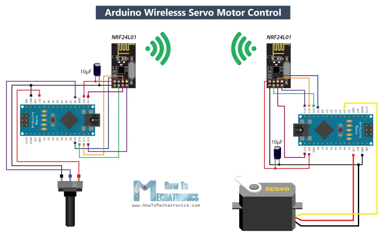
The receive side the NRF24L01 is connected to D9 to D13, and each servo needs a PWM pin. Only 3, 5 & 6 are available.
That makes 3 servos the absolute limit for the Uno, if you want more, then you will have to buy an Arduino Mega.